I’m creating a light show for a small (2-foot) Christmas tree. The lights I’m using are battery-powered LED light strands which I’ve cut the battery pack off of and am instead attaching the lights directly to an Arduino microcontroller, but I’m having some trouble figuring out power requirements and if I’m going to be able to make this whole thing work.
Here’s where my confusion lies: as an example, one of the strands has 30 small LED lights in series. The battery pack has 4 AA batteries and a 7.5 ohm resistor. Using Ohm’s law I calculated the current is 800 mA, which seemed high, until I realized I was neglecting the resistance of each LED in the circuit… When I used a multimeter I measured about 100 mA of current in the circuit, which sounds more reasonable (even though my microcontroller has a current limit of 40mA per pin).
But every time I’ve used one of those online calculators to figure out what resistance I need, it ended up telling me my source voltage (~6 volts from the 4 AA batteries) was insufficient to drive all those LEDs (which sites say are about a 2-volt drop each). So how does this circuit work in the first place (before I even get rid of the batteries)?
And given the Ardunio’s limitations (it delivers 5 V with a max current draw of 40 mA per pin), am I going to be able to control these LEDs with reasonable brightness? Any other tips/guidance would be helpful!
Are you sure the LEDs in the string are in series? Maybe they look that way but they might actually be wired in parallel or some combination of parallel and series.
Are you certain that there is no other circuitry in the battery pack other than the batteries? They could have a small DC to DC voltage converter that boosts the voltage to a much higher level, for example. Either that or your LEDs probably aren’t all in series.
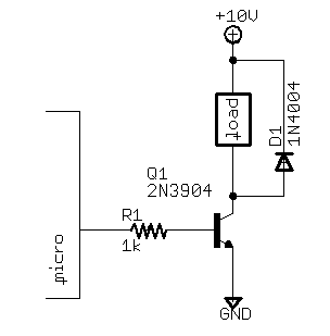
If you want to drive more current from your microcontroller, just add a transistor on its output. Your +5 will go to the + connection of your LED strand, the - connection of the LED strand will go to the collector of the transistor, and the emitter goes to ground. You want a resistor between the microcontroller’s output pin and the transistor base. The value of this resistor isn’t critical as long as enough current flows through it to drive the transistor into saturation when the microcontroller’s output turns on.
If you are having trouble picturing it, it’s something like this:
The load in that diagram is your LED strand. You don’t need the diode that they have pictured there.
If you are driving a relay or any other type of inductive load like a motor, a reverse biased diode such as the one in that diagram is used for when the load turns off. Inductors store energy in magnetic fields, and when you turn the device off, that magnetic field collapses and releases energy back into the circuit. That energy has to go somewhere, and the diode gives it a place to go. Without it, that energy tends to back feed into your microcontroller which can cause all kinds of damage. LEDs aren’t inductive, so you don’t need the diode in your case.
Let’s assume they’re red. And let’s say the battery pack is 5.9 V when operating. If the current through the battery is 100 mA, then there would be 0.75 V across the 7.5 Ω resistor. The 30 LEDs would therefore have 5.15 V across it.
A red LED has a forward voltage drop of around 1.7 V when a current of 10 mA is used. Which means the 30 LEDs must be arranged in a parallel-series fashion; a good guess is that there are ten strings of LEDs in parallel, and each string consists of three LEDs in series. Each string has 10 mA going through it. (This assumes there is not a DC-to-DC voltage converter in the circuit.)
At any rate, **ECG **is correct… the best way to control the LEDs is to use a transistor as a switch. I would use a TIP31 bipolar transistor or logic-level MOSFET in a TO-220 package.
If you really want to be cool, ditch the resistor and use an LM317 configured as a 100 mA current source…
IIRC my elementary electronics rules-of-thumbs, figure on a semiconductor diode (LED or not) being a 1.1 to 1.5 drop. 6V will not possibly drive an LED set in series unless it is only 4 of them.
You can do the transistor trick, or more simply have each control output drive a mini-relay that carries enough voltage/current to drive the necessary LEDs. that way the electronic control is isolated from the LEDs.
I suspect the previous posts are correct, and the voltage is boosted if there is no possibility it is wired in parallel. Test this by rewiring the strand the way it started out and looking at the output voltage of the box’s wires, since you have the wires cut and bare anyway.
Unlikely - driving LEDs directly from logic pins is rarely satisfactory.
But it should not be difficult to do what you want. Via the Arduino Forum linked by Rain Soaked I quickly found this tutorial on using the Arduino to drive a high-current load. The basic idea is, as Crafter Man suggests, to use the Arduino to control a transistor that supplies the necessary current to the ultimate load.
Oh, please.
This is simply not true. Almost all micro controllers have port pins that can sink 20mA, which is more than enough to drive even a high-brightness LED, and this is done all the time.
Now, in this case, it’s pretty clear that you can’t drive a string of LEDs off of a port pin, but please don’t assume that this is the usual case.
Okay, I went out and bought another set to look at the construction, and it does appear everyone was right in supposing they weren’t truly in series. Here are some pics of a LED and the battery pack (this was a set of purple, pink, and blue LEDs that doesn’t seem to have a resistor in the battery pack):
I’m fine with using a transistor, although I’ll need to get some more. I was going to use PWM to do some dimming effects - can I still do this with a transistor? Logically it seems like I should be able to…
I measured the voltage coming out of the battery box with 4 AA batteries and it was 6.3 V, so it doesn’t appear they’re using any kind of DC converter.
Another question: can I just measure the resistance of a light strand with a multimeter and get an equivalent resistance that I can then use in my V=IR calculations without having to think about voltage drops and the LEDs being in series or parallel? Or is the 9V in my multimeter going to cause trouble?
Oh, and thanks to everyone for all the help! I did cross-post this question to the Arduino forums (before I posted here actually) and the responses I got there were far less informative/helpful.
Yes, you can PWM with a transistor.
No, you can’t measure the resistance of the string with a meter (the meter voltage is unlikely to be high enough if the first place). Just measure the voltage drop across the LED string (not including the resistor) when they are operating.
Re PWM - Don’t make the frequency too low or you’ll have noticeable flicker. Below 15 Hz is visible to most folks. Above 100 Hz is smooth to almost everyone. On the high end, the capacitance and slew rate of your transistor will limit the PWM frequency. Unless you are really driving the thing fast this won’t be an issue.
FYI - You can overdrive the LEDs with PWM and they will appear to be brighter than they actually are. Your eyes tend to sense the max brightness instead of the average. Most LED alarm clocks these days and many other types of LED displays do this. Your eyes are a bit odd with perceived brightness and PWM but if you reduce the on time enough the LED will appear to get dimmer. It just probably won’t be the nice linear relationship between on time and brightness that you expect.
As beowulff said, you can’t measure the resistance with a meter. Diodes have a very non-linear voltage and current relationship, so the effective “resistance” at one current level will not be the same as at another current level. People often model a diode as a simple voltage drop, or maybe a resistor in series with a constant voltage drop. In actuality the voltage and current are related exponentially. You can use the voltage and current curves to come up with more exact calculations with respect to voltage and current, but the quick and dirty rough calculations most folks use are usually adequate.
Did some more checking. If you want to use an LED driver chip such as those made by Linear, TI, Maxim, etc., be aware that many of them are designed for high brightness/high current LEDs, which is not what you have. The LED drivers designed to control & dim lower power LEDs (10 mA to 30 mA) are more rare. Looks like the LT3746 by Linear Technology might do the trick.
“More than enough” being the key. Logic outputs are normally NOT current limited, and the max output spec is the hold rating of a silicon fuse, so you need to drive the LED via a series current limiting resistor, to protect both the output and the LED.
This you, and even I, might well consider “direct drive”, but anyone asking the questions of the OP probably needs the distinction made that you need to limit the driving current to the LED, and a logic output won’t do that if you connect the LED directly between the output pin and one or the other supply rail. A resistor in series with the LED of about 220 - 470 ohms works well for 5V supplied logic, and typical LED forward voltage and recommended operating current ratings.
Yes, even when using logic level outputs, you still want to use a current-limiting resistor when driving an LED.
A standard or LS TTL gate can’t source enough current to drive your garden-variety LED. But it may be able to sink enough current to drive one. HC, HCT, and CMOS may be able to sink or source enough current to drive an LED; check the datasheet.
Except when using a constant current source, such as an LM317.