There are a lot of different types of power supply circuits.
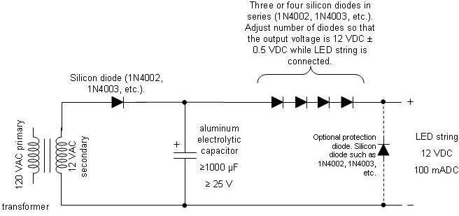
You could just stick a capacitor on the end of your single diode, like this circuit:
http://www.electronic-circuits-for-hobbyists.com/images/half-wave-rectifier-circuit-diagram.JPG
This circuit actually works fine for some applications, and it has the advantage of being very simple and very cheap. The disadvantage is that the single diode makes what is called a half-wave rectifier, meaning that it simply chops off and ignores the negative half of the AC sine wave. This makes it less efficient than a full wave rectifier and it will also be able to supply less DC power than a full wave rectifier, all other things being equal. The filter capacitor also has to be larger than the filter capacitor in a full wave rectifier, since it has to hold up the voltage for a longer period of time.
It also has a disadvantage in that there is no voltage regulation at all in it. AC power in your house isn’t 120 volts exactly (or 220 depending where you are in the world). If the power company guarantees 120 +/- 5 percent, then the voltage could be anywhere from 112 to 126 volts. This would mean your AC output of your transformer would be anywhere from 11.2 to 12.6 volts. Some circuits don’t mind that much variation. Other circuits want that 12 volts to be very close to 12 volts.
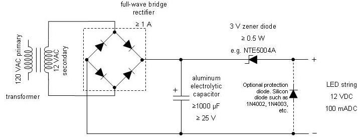
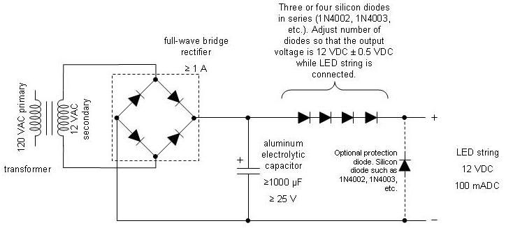
You can also use four diodes to make a full wave rectifier, like this circuit:

This has the advantage of using the entire AC wave, which means it can supply more power and it requires a smaller filter capacitor than the half wave rectifier above. It still has the disadvantage of not having any regulation in it, so the output voltage will still vary with the input AC voltage.
If you want your 12 volts to be 12 volts, and not somewhere between 11 and 13 volts, then you can add a voltage regulator, like the top circuit here:
http://www.dwengo.org/sites/default/files/domotics_circuit_0.png
You have to be careful with this, as most voltage regulators will not regulate all they way “to the rail” (up to the supply voltage). Most of them need to be a volt or two above their output voltage. If you try to drive a 12 volt regulator off of a voltage that varies between 12 and 14 volts you are going to find that it doesn’t work properly.
About capacitors: An electrolytic capacitor is good for the bulk filtering, but they don’t work very well at high frequencies. Ceramic disk capacitors work very well at high frequencies, but they are too small to be used for bulk filtering. Many power supply circuits will therefore use both types of capacitors in parallel, with the big electrolytic doing the bulk of the work and the small ceramic making sure you don’t get any high frequency weirdness.
Also keep in mind that a full wave or half wave rectifier alone, with a capacitor filter, is going to have a voltage fairly close to the peak voltage, not the average (RMS) voltage. So if you have a 12 VAC transformer output, the peak output is up close to 17 volts. Factoring in the voltage drop of your diodes and the ripple in your filter capacitor and the output voltage will probably be hovering somewhere around 15 to 16 volts. ETA: But again, without a regulator this voltage will be higher or lower depending on the AC supply voltage, so it could be anywhere between maybe 14 to 17 volts or so.