Ah, but that requires instant data transmission. The pulses have width=BBs per microsecond and the process takes time, so more than one pulse is propagating simultaneously. 101 = 10 BBs 10 no-BBs 10 BBs all on the wire
The transmission doesn’t have to be instantaneous.
It just has a “propagation delay.”
Just like an actual transmission line:
In physics, particularly in the electromagnetic field, the propagation delay is the length of time it takes for a signal to travel to its destination. For example, in the case of an electric signal, it is the time taken for the signal to travel through a wire. See also velocity factor and radio propagation.
IMO, when you’re talking about “data transmission,” the last thing you should be concerned with is electrons. They’re way down in the weeds. May as well bring the Heisenberg uncertainty principle in to it. Unless your inquiry is strictly for curiosity’s sake, I would ignore them.
And as we’re all aware, the transmission can’t be instantaneous. The “signal” when pushing BBs through a tube has finite speed. And the speed of the signal down a coax cable, for example, is around 0.7C give-or-take-a-few. Damn fast, but not instantaneous.
Data is encoded by modulating the energy flow down the cable. The precise nature of modulation is simply a matter of engineering, but so long as the wire can carry modulation with enough bandwidth and signal to noise, you can transfer any amount of data.
The signal cannot flow if there are no free electrons. We can contrast a wire made of plastic to a wire made of metal. The distinguishing feature that separates the metal from other materials is that is contains easily displaced electrons.
We can start right from the beginning. Ordinary matter as we know it is made from three things, protons, neutrons and electrons. Get a bunch of protons together, add about the same number of neutrons to them and the protons will be nicely bound into a tiny bundle of positive charge that we can otherwise ignore. Now add the same number of electrons as we had protons, and the electrons will settle into shells around the nucleus in an arraignment governed by quantum mechanics, basically the wave equation and the Paulli exclusion principle. So you basically get a tiny positive centre with all the mass, and a cloud of electrons around it, with certain interesting properties. At a distance the charges balance and the atom looks electrically neutral.
If you have a single atom, and you bring an electron near it, the atom ceases to look perfectly symmetric, the electron will find itself nearer to some of the outer electrons than the nucleus, and it will see a net negative charge, which will repel the electron. The same happens with another atom. Some elements have a smaller number of electrons in their outer shell, or the shell is large, and some of the electrons are not so well bound to the nucleus as others. If you assemble a lot of atoms of such elements together they tend to stick together in a matrix of alternating positive (atoms) and negative (free electrons.) You also get some level of covalent bonding, where atoms share electrons in their outer shells, which provides additional bonding. But metals all have free electrons. These electrons will move in response to an external electrostatic potential.
If I have a long length of metal, in principle every charge influences every other charge, but nearby charges have the property of overwhelming further away charges and thus nearby electrons tend to shield an electron from anything but very nearby potential fields.
If I have a wire, and in the example of a signalling line, two wires, say a twisted pair, if I apply a potential difference across one end of the pair, and the other end of the pair is terminated into a load, I can drive a signal down the wire. A potential field appears at one end of one of the wires, and say it is negative wrt the rest of the wire. That potential will push on electrons at the end of the wire. A free electron will move ever so slightly in response to the field. The field seen by its neighbour thus changes, and that electron moves, ever so slightly, and, as has been described earlier, a pulse runs down the wire. It is a lot like building a Newtons cradle with a huge number of balls in a line. On the other end of the circuit (ie up though the load and back again to the transmitter) we can apply a positive charge, that will attract nearby electrons in the wire, and an equivalent pulse will run down the wire towards the load, but with electrons moving towards the source instead of away. At the load (in an ideal system) we basically adsorb the pulse. The two pulses, one positive going, the other negative going arrive at the end and a potential difference appears at the load. One wire pulls back ever so slightly on electrons in the load, and the other wire pushes ever so slightly on the load, and thus a potential difference is received, that we can detect and resolve into a signal.
So how fast does this pulse move? Well clearly the mediating force between electrons is the electrostatic force, which is mediated by photons. So the signal between electrons moves at c. So why don’t the massive electrons move far too slowly to allow the signal to propagate at any useful speed? Basically because they are not point masses. They are a wave function that interacts with all the other wave functions.
What determines the speed of the signal in say a twisted pair is the coupled electromagnetic field of the two constituent wires. There is of course an external field to the wires. As the frequency rises this takes on a greater importance. But the two wires are coupled both magnetically and electro statically. Charge in one conductor will affect charge in the other, and moving electrons in one will create a magnetic field that couples to the other wire and induces current in it. Wires also couple to themselves. In the end you end up with what looks like an infinite set of capacitors and mutually coupled inductors all the way down the pair of wires. The same for coax, but with different values. This coupling acts to limit the propagation velocity of the wave to some fraction of c. Usually in the range 0.6 to 0.8.
Encoding of data can be done in all sorts of ways. The simplest is a clocked series of on/off pulses. Both ends agree on a data rate, and both set their clocks running. The sender turns the voltage on for a one, and off for a zero. The receiver keeps track, looking every clock tick and grabbing either ones or zeros. You can place a higher level protocol over this. Say you want to send eight bit characters. You define a sequence of say 11 bits. A couple of one bits says - there is a character coming, something that usefully might let the receiver synchronise its clock. Then you send the 8 bits of data, then send another one bit to terminate the sequence. The gaps between characters can then be any length you like. There is a nuance here. It is bad idea to send data as on and off, as the average voltage is not zero, but some intermediate positive voltage, and you can end up with nasty surprises with real world wires. Such as electrolytic corrosion. So encodings are designed that are more clever. You can make the pulses go positive and negative. Coding schemes were worked out decades ago for this. RS-232 and RS-423 are well known versions.
Modern systems are much more interesting. With enough care we can use multiple voltage levels, not just on and off. Also, since we use a clocked signal we can note that phase relative to the clock can be detected. So you can place a signal transition into any of the four quadrants of a complex plane, and get a lot more data values on each transition. This is quadrature modulation, and is ubiquitous. Your internet modem you read this over almost certainly uses this coding.
OK, so the electron flow analogy can be shoe horned into a twisted pair or co-ax. But, this is really hole flow. A single electron does not start at the input and emerge at the output. Each free electron shakes hands with it’s neighbor, which then turns and shakes hands with it’s neighbor and so on to the end of the line.
But, the propagation rate is a function of the inductance and capacitance per unit length of the conductor, not just c. And what we see at the input depends on the terminating impedance. If it is not the characteristic impedance of the twisted pair you will get a reflection back down the wire to the input. Do the electrons bonce?
And, in the case of an antenna where do the electrons go? Are they emitted from the tip? That always bothered me when presenting electron flow to a class, but I never had a student ask the question.
Excellent writeup, @Francis_Vaughan. This is why I love the Dope. ![]()
I did want to add something about the fields in transmission lines. For two, parallel wires (e.g. twisted-pair), I believe the fields spew out everywhere: between the wires, outside the wires, etc. The good news for this arrangement is that the losses tend to be very low. The bad news is that any conductor(s) in the vicinity of the two wires can “mess up” the fields that are extending outside the wires, causing a disruption in the VSWR and thus causing reflections.
It’s the opposite for a coax cable. For a coax cable, the fields are tightly confined between the center conductor and cylindrical shield. This mean the cable is mostly unaffected by nearby conductors. The bad news is that it tends to be more lossy than two wires.
No. They’re not “going” anywhere. Because the current is AC, the mobile electrons in the metal conductors are just moving back and forth.
Remember - you don’t need to have electrons “touching” (like, in a wire), to pass energy. If you did, a transformer wouldn’t work, since there is no “electrical” path from primary to secondary. Antennas are just a specialized case of a transformer - the energy is emitted from the transmitter’s antenna as an electromagnetic field, and picked up by the receiver and turned into voltage and current.
The electrons oscillate in the antenna. A radio antenna is a device that is designed to create a propagating EM field. Moving electrons in the antenna create magnetic field as they move. Also electrons create a electric field as they pile up at one end or the other of the antenna. This is a critical aspect of an antenna. The frequencies involved in radio are such that there is a clear phase difference as you go along the length of an antenna element. If we take a simple centre fed dipole we have an antenna that is half a wavelength long. (Pedantically it is electrically a half wavelength long, end effects act to make the physical wire appear slightly longer.) We feed a signal into the middle of the dipole. The dipole does not form a full circuit, but it does not need to. If we start with the rising slope of the waveform on one side, the other side will be being fed with the inverse signal, so a falling slope - which is the same as the signal 180 degrees out of phase. As time progresses the potential fed in from the middle propagates out at essentially the speed of light towards the ends. So there is a building electric field around the length of the antenna, and thus there is an extended electric field, one side positive, one side negative around the antenna. Changes in this field propagate away at c.
At the same time the electrons moving in the antenna create a magnetic field. Same deal, this field changes as we look down the length of the antenna since in the antenna wire at different points down the wire the electrons are moving in different directions and a different speeds. The interesting thing is that where the electric potential is highest is where the movement of electrons is the least, and thus the magnetic field is the least, and where the electric potential is the least, electron movement is the highest and thus the magnetic field is the strongest. All the time as the signal oscillates the electric and magnetic fields are building and falling and propagating away from the antenna at c.
In the antenna itself, by the time the building electrostatic potential has reached the end of the antenna, the cycle has come around far enough that at the feed point the potential has reversed, and current flow reverses, and so on. Electrons flow back and forth in the antenna, but because the polarity reverses at a rate similar to the time propagating wave reaches then ends of the antenna (exact antenna lengths get a bit complex depending on feed line impedance, geometry, and such) the device powering continues to deliver energy into the antenna. (Simplistically, it swaps polarity fast enough that the news never gets to the end of the antenna before it is time to reverse direction yet again.)
Crucially we can’t just modify the magnetic field of space with no effort. Even empty space presents some impedance to change. This is the permittivity (magnetic) and permissibility (electrostatic) of space. So pushing a changing electric and magnetic field out into space requires energy to be input. We see this reflected back to the transmitter as the antenna’s impedance, requiring volts and amps delivered to the antenna to radiate watts worth of power.
Our propagating electric and magnetic fields race together out into space, all the time maintaining their interesting spatial phase relationship. (There is some deep physics I’m glossing over here.) If they encounter another antenna, they can reverse the process, and deliver a tiny bit of energy to a receiver. Which is why transmitting and receiving antennae can be identical in design.
Fabulously, the permittivity and permeability of space clearly define the manner by which an electromagnetic wave propagates through empty space. together they define the speed of propagation, and the answer they give is indeed the speed of light.
The notion of phase differences between potential, current, magnetic and electrostatic fields in both time and space is critical for any useful understanding.
Another excellent writeup.
Well, it’s true each conductor of the dipole comes to a “dead end.” But there’s capacitance between the two conductors, thus there is a “full circuit.” At least I believe that’s correct.
Threads like this make me glad I was trained as just an ordinary commercial/residential electrician.
The issue under discussion is the electron flow analogy. The equations work, the analogy doesn’t.
In an improperly terminated coax, how do the electrons move in both directions to propagate a reflected wave around an incoming wave? How do they bunch up on the end of an antenna? How does the ‘one in/one out’ analogy work in a distributed amplifier?
BTW: The modern way around it - like when an electron has to cross some barrier, like in tunneling, is to think of it as a wave and once across a barrier switch back to electron or better particle.
I would recommend J D Jackson’s amazing classic to anyone wanting to get a good grasp on electrodynamics, but from what I’ve seen you write it might be worthwhile going back to something more elementary/undergraduate like Griffiths as suggested above.
It’s an analogy. That means it’s a way of explaining something in terms of something else that’s more familiar.
Pretty much all analogies break down when faced with “edge” cases.
The water-flow, or “BB” analogy are pretty good for illustrating DC electricity flowing in a wire, but they become more and more removed from what is actually going on when faced with AC currents, especially those in the RF frequency range.
Amen!
They don’t, except to a very limited degree for a short time (after which they become sparse on the end, and repeat).
Electron flow isn’t an analogy: It’s a simple fact. They do flow, and if they didn’t, then no electrical device would work.
Gosh, that’s a universal positive.
The ‘one electron in one electron out’ rule requires a complete circuit. That is not provided by the open end of the antenna.
The propagation delay in a length of coax is determined by the inductance and capacitance per unit length not the speed of light. Selection of terminating resistance will cause pulses to be reflected back up the coax. These reflections may be in phase or out of phase with the transmitted pulse How can electron flow explain the reflections. And, how can electron flow explain how pulses of different phase travel simultaneously in both directions on a single length of coax? There is no change in the input.
Electron flow works great as a starting point, but it is just an analogy. Try designing a tunnel diode amplifier using electron flow. How does electron flow account for negative resistance?
Consider an AC circuit that contains a series capacitor and resistor (link). The current is the same everywhere in the circuit. Yet the mobile electrons in the wires do not jump between the two plates on the capacitor; electrons do not flow through the dielectric of the capacitor at all.
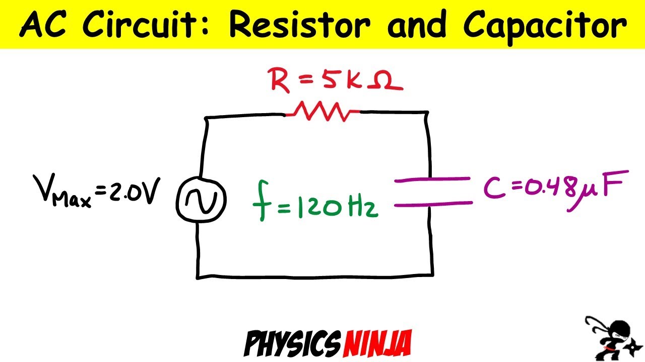
Sure, the analogy works great for simple RLC circuits. I didn’t say its not useful. Just that it is an analogy.