It means a person with an internal combustion car takes up the parking spot of a charging station, whether intentionally or not. The extension cord means the EV driver can park in an adjacent spot and still use the charger.
It’s when an internal combustion engine car parks in an EV charging spot to be a dick.
Try another hardware store? Maybe shop in a more expensive neighborhood? My hardware store carried a lot of “appliance grade” extension cords, suitable for devices that use a lot of current continuously, like a dehumidifier, and probably a car charger.
This looks like the way to go. Wire is 9 AWG (plenty heavy), plus interconnection is shrouded so more weatherproof than an extension cord.
Yeah, this actually seems like a great solution. Probably less likely to muck with the GFCI too. Thank you again @crazyjoe. I didn’t even know this was a possibility.
Ugh… some people.
Yeah, maybe, but it’s a smaller town with not that many options to begin with… they tend to sell middle-of-the-road options at quite a high markup. Fine for the typical lampcord, not really a great place to find heavy-duty specific kinds of cords at reasonable prices =/ At least here.
Actually, upon further review, I am not sure if these are necessarily safer anymore… =/ I’m having second thoughts.
It is a thicker gauge, but at 8-12A, that’s not going to be an issue regardless — level 1 is much easier to spec for than level 2.
But these J1772 extensions cannot be UL-listed because they are against code; the individual components (as in the cable, the connector, etc.) can be certified under different standards, but the assembly as a whole cannot. The manufacturers try to weasel-word around that, which doesn’t inspire trust ![]() This also means that the parts exposed to weather (like the part that plugs into the EV) will have to be a hack job, and it will depend on the manufacturer (as opposed to a certifying body) to make sure the connections between the cable, the charger head, and the EV are all safe.
This also means that the parts exposed to weather (like the part that plugs into the EV) will have to be a hack job, and it will depend on the manufacturer (as opposed to a certifying body) to make sure the connections between the cable, the charger head, and the EV are all safe.
So it’s a tradeoff between thicker wire (which is already overkill at 12/3) vs the UL-listed assembly of the standard household extension cord =/ Neither would be recommended… both are probably fine… the household one is much cheaper… hmm. Tradeoffs…
If I absolutely had to choose one or the other, I’d probably go with the J1772 extension. A NEMA 5-15 or 5-20 extension cord can and usually will be UL listed, but that has limited value considering how utterly terrible the plug design is: the ground doesn’t necessarily make contact first, the current-carrying prongs are exposed and can be touched while it’s plugged in part-way, and the weight of the cord largely pulls on the contacts (instead of the plug body itself). It’s entirely too easy for a plug that was built to spec and properly listed to shock the user through misuse or start arcing due to wear. Other countries recoil in horror at our plugs, but they’re not going anywhere in our lifetimes thanks to the sheer size of the installed base.
The J1772 design is far better: every pin and socket is individually shrouded so you can’t accidentally touch an exposed contact, ground connects first, there’s support so the contacts aren’t weight-bearing, there’s a latch, the plug isn’t energized until the EV and EVSE establish communications, etc.
The one main drawback with a J1772 extension is they’re unlikely to have the logic and hardware to keep their socket latched on to the incoming plug while current is flowing, so it’s possible to unplug them under load if you’re not careful. This could cause arc damage to the plug and socket.
You certainly would need to be careful about not buying the absolutely cheapest one and I probably wouldn’t use one for 48A+ charging in case the wire is undersized, but on a 15A or 20A circuit I think it’s less risky than a NEMA 5-series extension.
Agree.
Electrical ground power for some large aircraft have a simple but clever way of dealing with this. The cable between the ground power unit and aircraft contains six wires. Four of the wires are for power (three phase 115 VAC with center/neutral) and two are for an interlock circuit. Here is a photo of the cable, and here is a wiring diagram. When you plug the cable into the aircraft, the four pin-socket pairs for the power mate first. The two pin-socket pairs for the interlock mate last. The main contactor in the aircraft will be energized only when it “sees” that the interlock circuit is connected. This makes it impossible for the plug to be connected or disconnected when “hot,” thereby eliminating arcing. (This description of the circuitry is a bit over-simplistic and leaves out some details. See the wiring diagram for full details.) Not sure if EVs do this or not.
The level one charge cord for our Ionic 6 (new! we have an Ionic 5 as well) does disconnect based on the charge indicator in the door. I press the “latch” lever down and the charge light goes out before I even start to remove the plug.
As to the extension cord; a heavy duty 12/3 is fine, Care for water intrusion at the plug end is important as well as making a secure connection to the outlet. The sequence should be:
- Make sure the extension is plugged in securely at the outlet.
- Plug the level one charge cord into the extension cord.
- Set the charging rate on the level one box (if an option - it is on the Ionic).
- Plug into the car. Confirm charging starts.
- Unplug in the reverse order.
Well, this is concerning…
I got a power meter today, out of an abundance of caution and curiosity.
Turns out the EV, even when set to 8A charging, is actually drawing 15.5A at the outlet, according to that meter. If I set the EV to 16A or “MAX”, it draws so much current that the power meter shuts itself down (overcurrent protection after 16A)
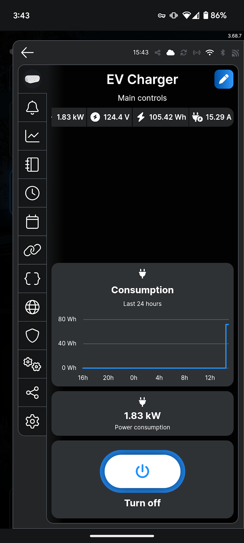
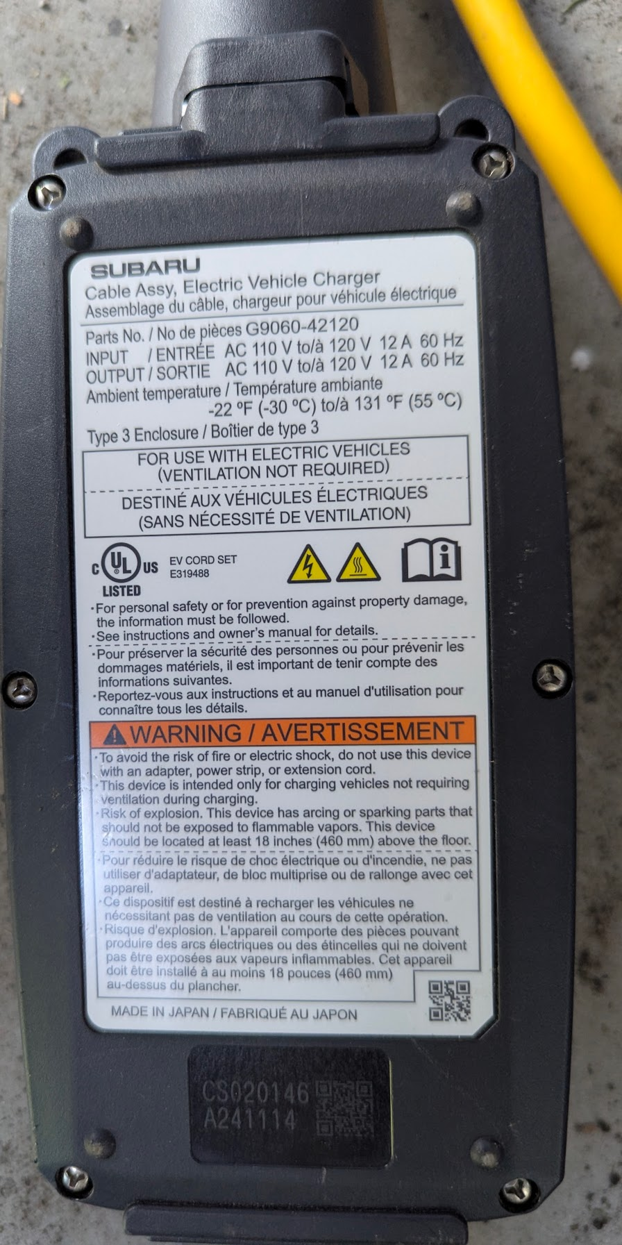
If the measurement is accurate, it’s pretty disconcerting. That means the supposed 8A setting is actually drawing nearly double that (at least at the outlet)… even though the charger itself says 12A max input:
Where’s the other 3.5A (or 400W+) going…? It can’t all be heat in the extension cord… that’s too much for any sort of normal efficiency loss… and the cord is only a 12/3 rated for 15A, not 15.5A continuous ![]()
But… the thing is… a few days ago, after a long trip, we accidentally forgot to reset the EV to 8A, and plugged it in at MAX amperage overnight. Nothing caught fire, thankfully.
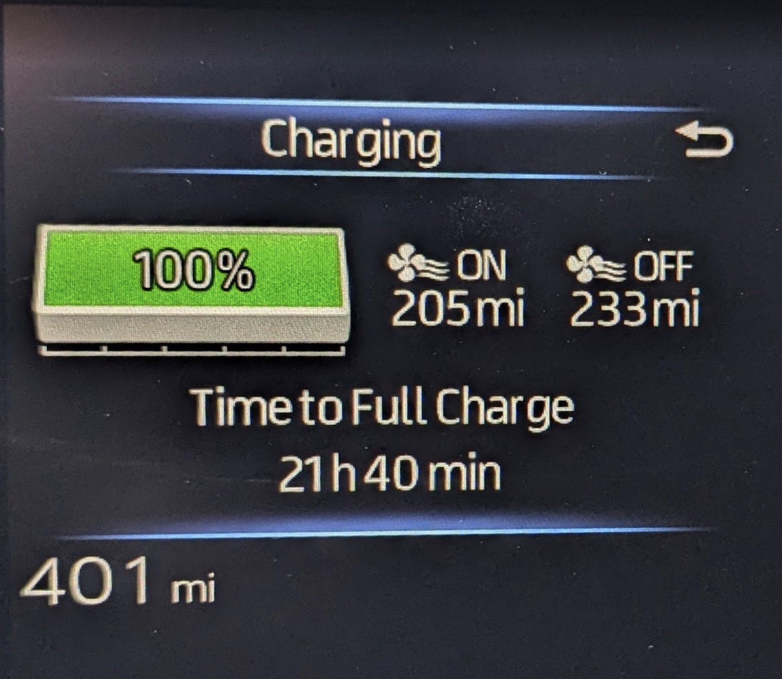
And even with 1.8kW charging, the car needs another 21 hrs to go from 100% to full… whatever that means…
Now I’m really confused, since none of the math adds up. Either the power meter is displaying an inaccurate reading, or something else is really wrong… ![]()
I had contacted an electrician a few weeks ago about adding L2 charging, but they never answered. Time to find another one…
That is pretty concerning. 15.5 A vs. 15 A isn’t a concern (the margin is very generous), but it certainly shouldn’t be drawing that much when set to 8 A.
Note that you can’t lose amps in an extension cord. There can be a voltage drop, which eats power, but if the source has an amp limit (instead of a power limit), everything upstream of that will also be at that amerage.
The charger box could use a small amount of current, but much less than an amp unless it’s defective. Charger boxes like these are basically a switch and some monitoring electronics, but otherwise a passthru. It isn’t doing any conversion on the electricity (that’s the car’s job).
I’d say the most likely scenario is that your power meter is giving bogus readings. It isn’t impossible for the car to be ignoring the current limit or something, but that seems less likely than it being the meter. Though it is possible that the car is drawing current in a way that confuses the meter.
This is also my best guess right now… if that weren’t the case, I suspect I’d already be too dead to do any guessing…
I’ll have to double-check this with another meter, or possibly one of those C-clamp transducer things… this can’t be right… very confused ![]()
Incidentally, I bought these recently, which are similar to yours but much cheaper:
So far they’re working well, but I’ve only tried them with my computer and monitor. And I haven’t had a chance to check against another source.
The Kill-a-Watt is basically the gold standard of consumer-level energy meters:
If you’re serious about checking power, it might be worth picking one up.
There are lots of ways to confuse energy meters, though. If the load has very spiky usage, the meter might not be able to sample it properly. They need to sample both current and voltage at a high rate, but even then it’s possible for some loads to give bad readings.
Try plugging some other high amp device, like a toaster oven or space heater, into the meter and see what the meter says compared to what the toaster says it should draw.
It’s worth doing as a sanity check (if it can’t get that right, it certainly won’t get the EV right), but those are simple resistive loads and will never confuse a meter unless it’s outright broken. So it could be that the toaster shows the right value but the EV still doesn’t.
Agree.
I believe the power meter is attempting to report RMS current. If it is simply dividing peak current by √2, well… that’s a problem for many loads, obviously. But even if it is using a more sophisticated method (e.g. ADC sampling or using a true RMS chip), the reading could be very inaccurate if the crest factor is large.
Suffice to say, a lot of modern electronics systems have really “wild” looking current waveforms, and measuring them can be a challenge.
Good call. I’ll run a few tests this weekend, and am also in comms with the power meter company to see what they say.
I have a SeaSonic PowerAngel, which I think has the same guts as the Kill-a-Watt. I wrote them a while back and they confirmed they perform V/I sampling and integrate the results. But I don’t know what these guys do. They seem pretty new, actually–smart switches with power monitoring. I’m going to tear one apart to see if I can figure out what they’re doing. I’d guess that they’re doing sampling, though, since the circuitry is so cheap these days. Any microcontroller that supports bluetooth/WiFi is going to have some ADCs on it and enough horsepower to sample and integrate.
Huh, that’s a new term to me. But yes, just that sort of effect is what I had in mind.
Yea, I’m pretty sure that’s how a lot of power meters work nowadays: to find average real power, they perform simultaneous sampling on I and V, multiply each IV pair (to get instantaneous power), and then average all the instantaneous power values over a 60 Hz cycle. Pretty simple, really. But as I’m sure you’re aware, things like sampling rate, jitter, bit depth, noise, accuracy of current shunt, etc. greatly affect accuracy, especially with the wild-looking current waveforms that are characteristic of many electronics-laden loads. A high crest factor with the current, for example, can cause significant quantization noise, resulting in considerable error. A Fluke 87 V costs $400, and can only handle crest factors less than 3. The power meter he’s using is $23.
OTOH, I’m not saying this is the problem, though. But just something to think about.
Agreed that it’s a likely problem.
Here’s a quick teardown of the smart plug meters I’m using (the TP-Link Tapo P115):

No oscilloscope measurements or anything unfortunately, but a comparison to a Kill-a-Watt. Seems to do ok even with a PF<1. It has a shunt resistor and what might be a voltage divider, so it’s probably doing some kind of V-I sampling. But as you say, waveforms can get arbitrarily ugly.