I’m glad to be reading that the issue is not completely settled.
When I was a kid, I went to a museum, and they had a wind tunnel showing the cross-section of an airplane wing. The docent asked if anyone knew what provided lift, and I said it was the angle of the wing, deflecting air downwards. They corrected me, and said it was the Bernoulli principle.
A lot of the confusion comes from the correlation … designing for good Bernoulli also designed for the pressure difference, lamina flow, and good lift vs drag. etc Its the way the WW2 wings were designed.. then looking at a modern wing, you reckon it might have a strong Bernoulli effect.
Meanwhile the various shapes like the 757’s wing shape are trade secrets. mach 0.8 speeds and above requires advanced designed .. plenty of wind tunnel testing… etc. They didnt have principles to guide them … they just tried designs… making trade secrets..
The 757 shows its the difference between pressure that matters. the pressure below doesn’t have to be high, but there has to be a pressure difference between below and above..
But for any case, Bernoulli or not, Newtons laws are obeyed, for the plane to fly the air has to be pushing the plane up, so the plane must push air down. For the 757 with 10 degree attack, this downward flow is well after the wing… The wing is pushed up into low pressure, but the overall result has to be net downward air flow (to have lift.)
Turbulence won’t appear immediately. Importantly turbulence isn’t what directly limits the availability of lift. What matters is when flow separates. Flow can be, and often is, turbulent and remain attached. Losses are higher, but lift isn’t lost.
Air is a fluid, so has mass (thus momentum) and viscosity. Even a laminar boundary layer will remain at non zero angles of attack, although only for shallow angles on a flat plate. As it transitions to turbulent flow the turbulent boundary layer will remain attached for higher angles and produce lift. It isn’t exactly fabulous, but paper planes and simple model planes do fly.
Scale helps, the smaller and slower things are, the lower the Reynolds number, and that makes things more benign. Which is why models do not directly scale up. Neither do full sized craft directly scale down. Low Reynolds number is why bumblebees can actually fly. (Flapping of wings helps too.)
Very clear indeed! And I had no idea the board supported LaTeX either - of course I haven’t used LaTeX since my dissertation, one-third of a century ago, so it would kinda be off my radar.
ETA: This is the sort of thread that makes it worth hanging around this joint.
Technologically, the board uses the MathJax engine. Which is LaTeX plus a bit and minus a bit. See TeX and LaTeX Support — MathJax 4.0 documentation for the gory details. Most of which won’t matter for simply rendering an algebra or calculus formula.
I retract my conclusions. The amount of lift generated by wing shape varies a lot with angle of attack - I can’t just assume it to be constant, which is what I did above. The correct calculation would superimpose a line for a barn door wing on the graph from wiki. That gap between the two lines would show the effects of improved wing shape on lift. I implicitly assumed such effects would be constant - that the two lines on the graph would be parallel. That assumption is not warranted, even as an approximation.
A better version of this approach would involve statistical analysis on wind tunnel data to control for possibly confounding factors such as wind speed, scale, etc.
That said, I retain some skepticism about the implication that wing shape matters only a small amount relative to angle of attack, pending a cite with statistical analysis of wind tunnel data. I’ve seen it on the web, but that might simply be a matter of careless reading on my part.
What I can say from the graph is that lift generated at zero angle of attack is not trivial. So wing shape matters at or near a zero angle of attack. I speculate that might apply to cruising speed (with low but positive angles of attack). I don’t want to speculate about takeoff.
It seems to me that if you’re getting lift at zero angle of attack, then you’re defining angle of attack wrong. Rotate a wing continuously from pointing straight down, to straight up. At some point in between, there will be an angle where the net lift is zero. That angle is zero angle of attack.
By convention, angle of attack (AOA) is defined as the angle between the freestream flow and the chord line of the wing. Which in turn is defined as a straight line drawn from the geometric center of the leading edge curve to the geometric center of the trailing edge curve.
For a symmetrical wing, or a flat plate barn door as a special case of symmetrical, lift will be zero when AOA is zero. As you suggest. Otherwise at zero AOA the lift is whatever is due to the assymetry.
All of this is purely definitional. In a different timeline it might have been defined as you suggest. I suspect, but do not know, that there’s actual computational simplicity in defining AOA as they do. Back in the day engineers, and physicists, of which aerodynamicists are a subset, were generally real careful to define their standard terms and standard variables for ease of computation.
A question I’ve never been able to find a straight answer to: Imagine a wing with perfect front-back symmetry, aligned so that the plane of symmetry is vertical. Put such a wing in a wind tunnel, and run the wind through the tunnel in either direction, and the lift would surely be the same in either direction, by symmetry. Is there any shape for such a wing such that the lift is nonzero?
All I know about how a plane flies is from many decades ago reading parts of the free online book See How It Flies, and I want to plug that book. I kind of gloss over the equations, but it’s taught me many things about flying, such as the yolk controls airspeed, and that calibrated airspeed is a direct measure of angle of attack.
Looking through it now, it makes the claim that camber (the to curvature of the wing) is there because it makes the wing more resistant to stall at high angles of attack (I’m condensing into one sentence whole sections of the book, so I probably got something wrong).
We have seen that under ordinary conditions, the amount of lift produced by a wing depends on the angle of attack, but hardly depends at all on the amount of camber. This makes sense. In fact, the airplane would be unflyable if the coefficient of lift were determined solely by the shape of the wing. Since the amount of camber doesn’t often change in flight, there would be no way to change the coefficient of lift. The airplane could only support its weight at one special airspeed, and would be unstable and uncontrollable. In reality, the pilot (and the trim system) continually regulate the amount of lift by regulating the all-important angle of attack; see chapter 2 and chapter 6.
The shape of the wing determines how much lift it is capable of producing at each possible AOA from massively negative to massively positive. The shape of the wing also determines at what airspeeds it can produce how much lift. So for a given wing size & shape, Lift = f(Airspeed, AOA). The engineer’s job is to decide a size and a shape that makes sense for the work the wing is expected to do.
Which wing size and shape determines the size and shape of the lift envelope: how specifically the lift varies by AOA and what the upper & lower speed limits are. The wing of a competition STOL prop plane and a jet fighter are each carefully chosen and informed by the same science. But their envelope shapes are wildly different because the work they’re expected to do is wildly different.
The pilot controls how much airspeed and how much AOA is applied to the engineer’s wing at any given moment. Which in turn determines how much lift the wing is producing at any given moment. Whichever wing shape the pilot is dealing with.
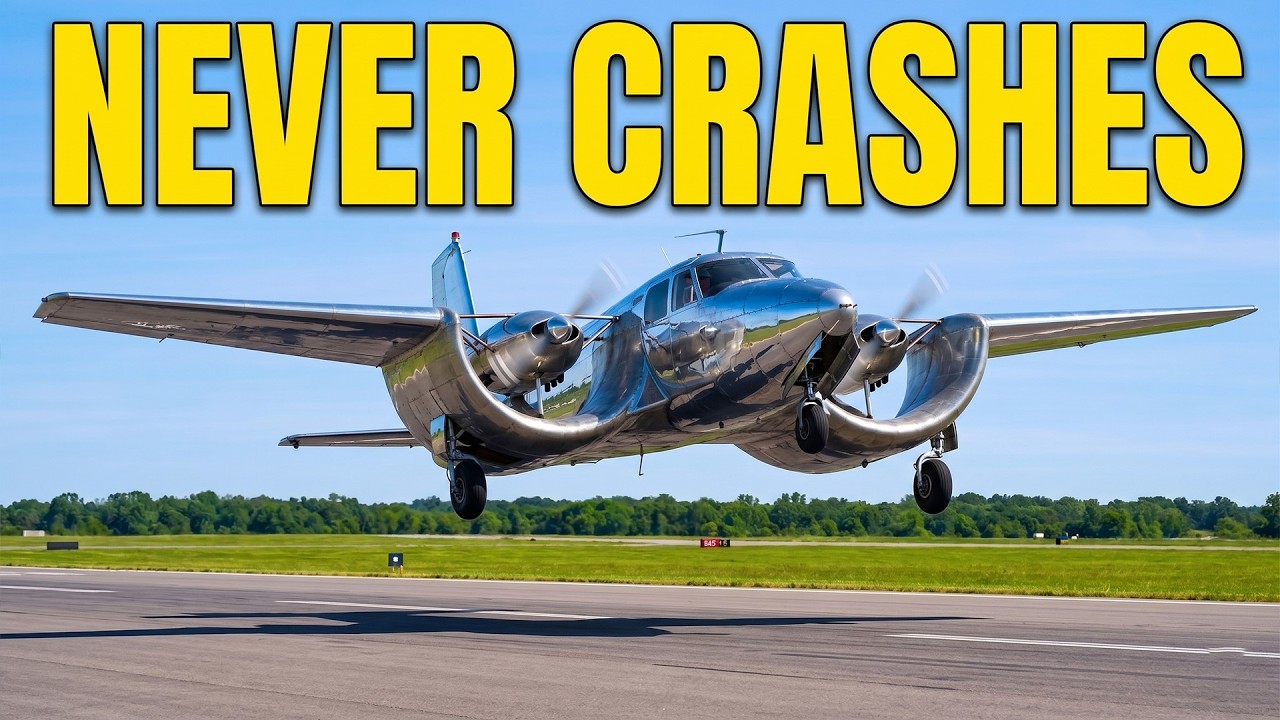
I wonder what its flight characteristics with an engine out would be like. Especially trying to land it on one engine. My suspicion is that that problem alone might be enough to make the idea unviable for any form of conventional use.
The logical end-point is a fully blown wing. Something that remains a research idea, but not impossible. With many small electric motors a fully blown wing would sidestep issues of single engine failures.
The point of the U-wing design was simply to increase the amount of wingspan that was close to the prop tips. Since the prop tips form a circle, the wing had to be bent into a circle. If you kept the semi-circular well in the wing but raised the engines and props to be above the well, you’re undoing the value of having built the well into the wing.
I like how the title of the vid is “Why Everyone wants this U Wing …” and in fact no one does. Yes, I know that was the title of a historical article, but still.
As you say, one of the neat things about an electric airplane is the ability to decouple production of power from application of power. IOW, put a hefty engine (or two) turning a single central generator (or two), or equally a large battery, someplace aboard then distribute the power to several to dozens of distinct motors & props. The failure of any one, or even several, of the much smaller prop/motors would be much less of a deal.
I observe that there is a similar confusion with the Foucault pendulum. Is the Coriolis Force a cause, or a description? What exactly is the Coriolis effect on the Foucault pendulm, and does invoking Coriolis add anything to the explanation…