I understand that light comes in packets called photons, which have two waves associated with each packet, a magnetic and an electrical wave. My question really is about the direction of the wave though. In the textbooks the waves are drawn as running along the path of the photon in its travel. if the photon is drawn going left to right, the waves are drawn with amplitudes of vertical and horizontal.
However, when you ask about the screen on the front of a microwave, you’re told that it blocks the escape of the microwaves, because the wavelength is too long to fit through the holes. But the actual length of the wave is always drawn along the path of the travel.
I can have a long wave with a small amplitude, which according to the textbook diagrams would then fit through the hole. There seems to be then the concept of the wavelength existing perpendicular to the path of travel. Is that right?
I stumped my MIT engineer dad with this one, because it doesn’t come up in manufacturing engineering.
I asked this of my former co-worker, who has a U Cal Irvine physics B.S., and got only guesses.
He said that one photon can’t have a wavelength on its own. What?
He guessed that maybe the screen is not reflecting the waves, but just letting them out a hole small enough that the transmission to the other side makes for a wide angle of spreading out, which reduces the intensity of the photons hitting the people. That one sounds off to me, because there are so many holes letting the waves through, and I’ve never been warned not to stand next to a microwave.
There was also something mentioned about high energy waves having more interaction with the electrons of the barrier, and maybe it’s not the wavelength that’s the problem, but the higher energy itself that makes it hard for the waves to get through the holes.
[ol]
[li]You don’t have a long wave, because they all travel at the speed of light[/li][li]Typical microwave ovens have a wave length of 12 cm (~4 in), which means that they have a complete “rotation” through phase space in 12 cm. Note that the mesh on a microwave is much much smaller than that, typically 1.2 cm or smaller.[/li][li]Ignore how they are drawn, EM radiation phase space is in the complex number world and the diagrams are simplified visualizations.[/li][li]Consider a polarizing filter is basically a lot of super thin finely spaced wires that block photons with a particular polarization.[/li][/ol].
This is a great interesting macroscopic effect of quantum mechanics. This video is the most accessible intro I personally know of.
But the textbook diagrams are attempts at visualizing phenomenon that are quantum in nature and the observations will not fit in with typical human intuition.
The probabilities involved result in the signal being so heavily attenuated that we call it “blocked”. Generally gaps being 1/10th of the wavelength, or smaller, will provide almost complete shielding.
It is more complex than that but that should be a start.
The wavelength is in the direction of propagation. But it can have effects in other directions. Whenever waves (of any sort, including familiar sorts like ocean waves) travel past obstructions, you get diffraction effects, which depend on the size of the obstacles and the wavelength. The net effect is that, yes, a mesh much smaller than the wavelength of a wave makes an effective barrier to the waves.
As Chronos rightly points out, light waves are three-dimensional in nature, and proper calculation requires that you take this into account when determining diffractive effects.
The Rainbow paper by Airy that I mentioned above contrasts the true three-dimensional interference effect you get from considering the entire wave, and compares it against the consequences of only considering rays traveling in one direction. The result is so skewed that the “one direction” results have maxima where the correct calculation has minima, and vice-versa. *
Since the waves propagate in three dimensions, you have to conclude that the wavelength exists in all directions, as well, and not just along the direction of travel.
*I did a column about this, too, for Optics and Photonics News. Sadly, it’s not available online unless you’re an OSA member. But you can see some plots here. They’re labeled “Young’s plots”, although Young never actually made these – they’re the result of blindly plugging some of Young’s ideas into the situation – http://www.philiplaven.com/Publications/AO-56-19-G104a.pdf
The fact that microwave radiation (or light) does not propagate through a small enough hole is not a quantum effect. It is completely explained by classical physics, i.e. Maxwell’s equations. The simplest geometry to think about is a small pipe with reflecting walls, a so-called waveguide. In that case, the math is pretty straightforward and you find that for pipes of a given size there is a cutoff wavelength. Waves shorter than that wavelength will propagate through the pipe, longer wavelengths will not. You can think of the holes in the microwave shield as “waveguides beyond cutoff”. Beyond cutoff, the amplitude of the waves will decay exponentially as you progress into the pipe.
Yes, the amplitude is drawn orthogonal to the direction of propagation, and yes, the arrow/line is drawn with a certain length.
This length represents the magnitude of the field at the point where the arrow starts.
It does not mean that the field has a physical extent in space.
If you draw a single arrow for field amplitude from a single point, the field is * only in this single point*. The points right next to it do not have any field whatsoever.
A photon is a point particle. It doesn’t make sense to say that a hole is to small for a photon.
A photon is not a point particle. It’s an idealization and its size depends on the physical system and how you choose your basis set. In a microwave cavity, a photon is a big as the cavity itself. In free space, it is infinite in size. Strictly speaking, photons are quantized energy states and completely static. If you want something dynamic, that moves from A to B, you need a superposition of photons.
The thing HeiLo is emphasising is that in your diagram the drawn vector is only representing the field at one point in space. If you want to know something about the point adjacent, you need another seperate arrow. (Things will get cluttered really fast). The points in space that the arrow appears to intersect in the diagrams are only intersected by bad luck due to the way the picture is drawn. The arrow is not representing anything about the field at any point other than the one at its origin. In reality there is no arrow. The arrow’s extent has no physical meaning other than a graphical representation of field strength. Nothing about the field at the point represented has a physical extent beyond that ideal point. Obviously we expect that the other points in space nearby do have a value for that field, and that there is some correlation in values. That correlation may well be in terms of wavelength and phase of some phenomena. And that correlation may well move in space and time. That is your wave.
Microwaves are transverse waves , so yes they oscillate perpendicular to their direction of motion.
A material that is reflective to a wave with holes smaller than the wavelength will be seen as a solid object.
The up and down visual drawing of a wave is just simplified graphics. Since it actually represents amplitude or essentially the power (not exactly but just to explain more simply) of something not necessarily its actual motion.
So even a sound wave can be drawn the same way, though in reality it is a longitudinal wave.
It oscillates in it’s direction of the travel. It’s more like a series of balls hitting one another (reflecting) and rolling back. Amplitude is attenuated with distance…
With transverse waves amplitude can be attenuated with transverse distance or size of a hole. Basically it just reflects back on itself too much to travel forward. Like in the waveguide example.
The particle size here is basically irellevant , thus is why visible light (photons) gets through just fine and you can see inside. At wavelengths measured in nM it has no problem passing through.
I agree, I expressed that rather badly, and you are correct.
Going back to the OPs question, what the mesh prevents is for the microwave fields inside to interact with a charged particles outside. That particle could be an electron in your body, the interaction would occur only with this electron, it would happen instantaneously, and it would transfer a definite amount of energy to the electron.
This combination (localized, instantaneous, fixed energy) is what the commonplace use of “photon” usually means. It actually describes an interaction, not propagation to the place of interaction.
If one is talking about photons, then they are no less dynamic than, say, electrons. A single photon is a real thing that has real energy (of any value) and can move from point A to point B.
This is in a similar vein. While photons are intimately related to electromagnetic interactions, a photon is definitely not an interaction. A photon is a fully fledged particle.
Tangent:
I watched the video and the explanation of how hidden variables don’t work to explain the A,B,C polarized filter effect, but it seems like there is an assumption being made that the hidden variable must be independent of other attributes of the system (time+space). (For those that didn’t watch the video: filter A+C at 45 degrees let’s through 50% of particles, but adding filter B at 22.5 degrees increases the particles let through).
The Venn diagram of the particles and whether they make it through filter A, B or C, assumes that the subsets of particles must be consistent, regardless of the configuration of filters and/or the path through them over time.
But what if the hidden variable is tied to the full end to end data of the system, through time and physical configuration. In other words, just because the Venn diagram can’t separate the particles to properly support both the A+C and the A+B+C filter configurations, there still could be some formula that correctly identifies each group of particles when all of time and physical aspects of universe are included.
Note: I do realize that smart people have this all figured out and I didn’t find a flaw in their system, just curious what the counter to this thought is.
3blue1brown is a master on making visual intuitions of math concepts.
I can’t figure out how to word the difference between group velocity and phase velocity, but this video about the uncertainty principle in classical scales.
While this animated gif is showing a phase faster than the group velocity, it provides an analogy that is better for a “wave packet”
While an imperfect analogy this very short video from the FloWave research wave tank demonstrating concentric wave spike may be one way to imagine how a wave becomes a “particle” although all of these analogies fall down here. But we have to work within the limits of our ability to visualize without quite enough degrees of freedom.
The particle wave duality of EM radiation is pretty hard for us humans to have an intuitive understanding of and to be honest some of the issues are unsolved. Remember that us humans can’t even imagine complex numbers even in less than 3 spacial dimensions and the phase space would involve imagining a hyper-sphere and still wouldn’t be exactly correct.
Really our limited ability to visualize intuitively and the added complexity of reducing that down to 2D makes us use simplified ideas with not enough degrees of freedom because we can’t really “print” the phase space for EM radiation.
Here is a wikipedia page on wave packets that may help.
The important part phase, group, and signal velocities are all separate concepts and simple sine wave drawings always lose information about this. A sine wave works in a “perfect vacuum” as the group velocity and phase velocity are identical. But when when you have charges that are in one place or kind of in one place like a perforated metal sheet or glass or air they will be different.
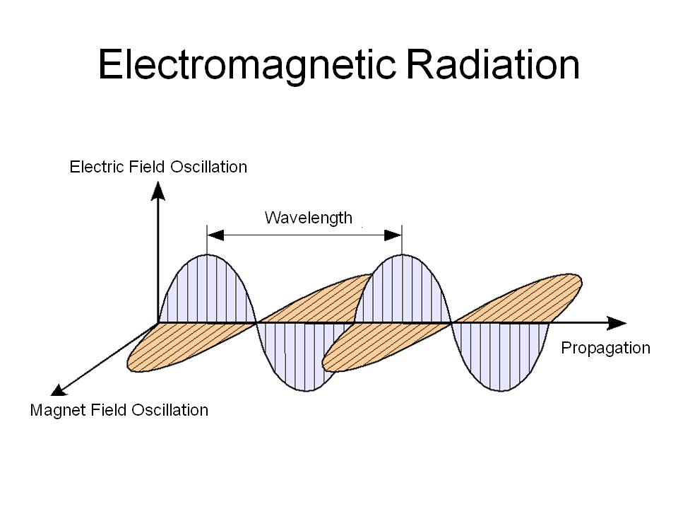
A “radio wave” is made up of an electric field and an associated magnetic field that are at a right angles to each other as well as to the direction of the forward movement. If you can observe the electric component or the magnetic component depends on your relative motion to the wave.
But let that sink in:
The electric field is orthogonal to the magnetic field
The electric fieldandmagnetic field are orthogonal to the direction of movement.
That is where you get this diagram.
But note that is a simple drawing with one spacial degree of freedom
Note that polarization is not always perpendicular to the direction of travel but for a massless spin-1 under gauge field theory like light or radio waves in a vacuum you can get away with two degrees of freedom, but in a medium the z direction of the electrical field will be effected but you can adjust for that and still get back to two degrees of freedom.
The intuitive correspondence of a sine wave “hitting” something just goes away.
What you have are boundary conditions from a conductive wall, here is a paper that covers several subjects and has simpler math but still not quite as simple as the sine wave in free space.
TL;DR: I think the OP “single photon can’t have a wavelength” is confusing the particle-wave duality. The “particle” form is from a wave packet and not a individual “peek” or cut off sine wave. But single photon is the particle like manifestation of the wave function, not a single truncated sine wave which wouldn’t even have a “frequency” due to the uncertainty principal even in a generalized form.
So the wave can be seen as a sort of sphere around the center of the wavelength, so the wavelength is measurable as half the wavelength in any direction and 180 degrees from that direction?


