A while back I purchased a new 24’ enclosed race car trailer. I’m finally getting around to installing cabinets, racks, and other things. I would also like it to have some 110v lighting and outlets. This will be powered from an external generator (well, inverter). This generator will be disconnected when not in use.
I will be doing the work myself. I have some basic ideas on what I need. There will most likely be three 4’ fluorescent lights. I would like at least two outlets. Load on the outlets will be things like fans, halogen lights, and small power tools. I’m talking stuff that would run off a 15A circuit combined.
I guess I’m thinking some kind of entry box with a breaker and then a conduit run down one side to the lights and outlets. I want to make sure this is wired correctly. I’m really concerned about grounding in particular. Thus, I’m asking the Dopers at large if anyone can lead me in the right direction?
First off more power is better. If you think you need 15A, build it for 20A. Sooner or later you will be glad you did.
You can fabricate a small area on the tongue where you can place a generator when you are at the track. The generator will have a circuit breaker, so there is no need to add an additional breaker to the system. You can run a short extension cord out of the trailer to plug into the generator*. This would also give you the advantage of being able to hook up to your shop power when you are not at the race track with just a extension cord.
I would put a box inside the trailer, and then run from there up to a switch and then to the lights. Also from that box run to the two outlets that you want to power.
I don’t think the NEC covers race car trailers. You could run Romex, or put the wires in conduit. If you want it to look really nice, or you have rats in your area, use conduit.
*You can do the power supply cord one of a couple different ways. You could cut say a 1" hole in the front of your trailer, and stick the extension cord though it. Personally I don’t care for this idea, as it will allow rain and shit to enter the trailer. I think a better way would be to mount a weatherproof box and cover on the outside of the trailer. Use a short nipple off the back of the box to attach it to another box on the inside of the trailer. Only instead of an outlet inside the cover, just have a 110V plug. Open the cover, attach a short extension cord to the plug and then into the generator. This also has the advantage of if you are plugged into shore power at your shop and it rains, you don’t have to stress about it.
ETA: Don’t buy the really cheap shop light, get the ones with fully enclosed plastic covers. That way if a tube does break, it does not shower the race car (and you) with fragments.
[QUOTE=Joey P]
Are you going to take the tubes out when the trailer is moving? It seems like a 4’ they’d wind up snapping when you hit a bump.
[/QUOTE]
Honestly, it seems like that to me too, but I see them in race car trailers all the time. It doesn’t seem to be an issue. That said, I don’t have much love for 4’ fluorescents. The cheap ones should go straight to the trash. These fixtures will not be a place to save money.
Rick, I’m not sure if I’m following the generator over an inverter. I’ve always heard that an inverter has cleaner power. One thing that I forgot in the first post is that a set of digital scales may be connected to this. RogueGF’s Powerbook is another possibility. Regarding the truck’s alternator, I agree that I don’t want to be replacing it. However, this wiring should be completely separate from the truck and trailer’s 12v system. What am I missing?
As far as the rest of the suggestions, they seem to make a lot of sense. Basically it simplifies what I had in mind and eliminates some possible issues. Thanks!
Sorry, but I did a really crappy job of composing and editing my post.
When I first read your post, I thought the inverter you mentioned was one of these that hooks to your alternator, and steps your voltage up to 110V and inverts it to AC. After I finished my post, I took your link, and saw what you were linking to. :smack:
So I cut out the paragraph out about using a generator instead of an inverter. :smack:
I used generator in the generic sense of a gas powered device that generates electricity. Feel free to sub in inverter where ever you see generator. My bad.
[QUOTE=Rick]
The generator will have a circuit breaker, so there is no need to add an additional breaker to the system.
[/QUOTE]
The breaker on the inverter/generator is to protect that device from overload. Other breakers may well be needed to protect the wire from catching fire. If your inverter will put out 2 KW, and you have 14AWG wire running to the lights, then you need a 15A breaker on that circuit, so the wire insulation does not burn up if a light fixture ballast malfunctions.
It would be a good Idea to include a distribution panel, with breakers for several circuits. That way if you have a short in one circuit, you can still use the other circuits.
Grounding with inverters can be a sticky issue. Some do not isolate the input from the output. That means that you MUST NOT connect neutral and ground, because the “neutral” connection is actually hot for half of the (pseudo) sine output. So if you do use a distribution panel, the neutral bus needs to be isolated from the enclosure. Such a box will be marked as “not for use as service equipment”.
Do you have an example of this nipple? How about a fixed 110v plug? I don’t know if I’ve ever seen that.
Thanks again!
[/QUOTE]
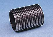
First off, a nipple is just a piece of conduit that’s threaded on both ends . The idea is, you put a hole in the trailer, but the nipple thorugh it, a box on each side of the nipple, then clamp it down on both sides. This will keep both boxes in place and provide a watertight passage from inside to outside. As for the plug…Wire up the trailer however you want, bring the wire that you want juice coming in from down to the box we just talked about (on the inside), run the wires to the outside (through the nipple) and wire a plug onto it. Then when you fire up the inverter you can run and extention cord from the inverter to this plug and your trailer is now hot. It’s simple, it works, it’s safe, and it’s mostly elegent.
[QUOTE=Kevbo]
The breaker on the inverter/generator is to protect that device from overload. Other breakers may well be needed to protect the wire from catching fire. If your inverter will put out 2 KW, and you have 14AWG wire running to the lights, then you need a 15A breaker on that circuit, so the wire insulation does not burn up if a light fixture ballast malfunctions.
[/QUOTE]
As they say, your mileage may vary. My generator has a 15A breaker for the 15A outlet, a 20A breaker for the 20A outlet, and a breaker for the 220 outlet (I don’t recall the size, as I don’t use that one) If I were putting my generator on a race car trailer, I don’t see the need for a redundant breaker. I guess it depends on how your generator is set up.
As Joey P said a nipple is just a short piece of threaded conduit/ pipe you would thread it into the back of one box, insert the nipple through a hole in the trailer, and then thread it into the back of a similar box inside the trailer. With a little bit of RTV silicone and a few screws you now have an waterproof connection from the outside to the inside of the trailer.
As far as the plug goes, Either buy a foot of heavy duty (#12 with 2 conductors +ground) extension cord type wire and wire a plug onto it, or cut a foot off of the male plug end of a heavy duty extension cord. In either event, stick the cord in from the outside and pull it though until the plug is inside the enclosure (see link in my first post). Using wire nuts, at the inner box, connect the wires from the plug to the trailer wiring.
[QUOTE=Kevbo]
Grounding with inverters can be a sticky issue. Some do not isolate the input from the output. That means that you MUST NOT connect neutral and ground, because the “neutral” connection is actually hot for half of the (pseudo) sine output. So if you do use a distribution panel, the neutral bus needs to be isolated from the enclosure. Such a box will be marked as “not for use as service equipment”.
[/QUOTE]
This was more what I was getting at with my OP. What you’re saying is that a panel would pretty much get wired like an expansion box in a house right? Ground is ground. The common rail is insulated (and isolated) from ground.
Joey P (and Rick I see on edit), ok, that makes sense now. For some reason I was thinking about something like a firewall passthrough like I have for the battery cable on the race car.
It sounds like the most correct way would be a panel for the trailer and use two circuits (lights, power). That said, if I go off the 20A GFI on the generator, I should be just fine using Rick and Joey P’s method as long as I use 12AWG wire for everything.
It’s a very good assumption that any given generator will not be grounded. Mine sits on rubber tires, and in the case of the one the OP links to, it’s got a (probably painted) metal pipe frame, but you can’t count on the incidental contact between it and the dirt to provide a useful ground connection.
Somewhere on the frame will be a ground terminal so you can connect the frame to a “made” earth ground such as a driven ground rod or a metal water pipe. In my case, the generator has a 4-blade twist-lock connector as it puts out 240/120. The frame is connected to this connector’s ground blade, but is otherwise uninvolved with the creation of electricity and is not tied to the neutral.
I’ve never grounded the generator’s frame, and rely on GFIs to provide safety for the humans. The generator has its own circuit breakers to protect itself. With or without a ground, GFIs will protect against shock, but you will need to label the receptacles as “No equipment ground” as there will be no ground available.
Also, the OP should be aware of the difference between parallel and series circuits when doing the wiring. All the wiring will be done in parallel, although if you don’t know what that means you may end up doing some or all of it wrong.
PM me if you need, I happen to be an electrician and can assist you from some simple pictures if you have the time to snap a few.
[QUOTE=RogueRacer]
This was more what I was getting at with my OP. What you’re saying is that a panel would pretty much get wired like an expansion box in a house right? Ground is ground. The common rail is insulated (and isolated) from ground.
[/QUOTE]
Exactly so! If you can pick the inverter up with one hand and or don’t need bank financing to purchase it, then it has no 60Hz isolation transformer, and you need to take this precaution. Only high end inverters (typically used with photovoltaic or wind powered systems) will be exceptions. Interestingly, the old Royer converter based inverters usually were isolated, but they were bulky and heavy, so have been supplanted by boost + H-bridge designs.
[QUOTE=Uncommon Sense]
Also, the OP should be aware of the difference between parallel and series circuits when doing the wiring. All the wiring will be done in parallel, although if you don’t know what that means you may end up doing some or all of it wrong.
PM me if you need, I happen to be an electrician and can assist you from some simple pictures if you have the time to snap a few.
[/QUOTE]
Thanks for the offer. If I run into something I’ll take you up on it. That said, I do have a BS in electronic engineering, so I should have the parallel vs. series thing covered. I’m still aware that I’m no where close to being an electrician though. In fact, the parallel/series thing reminds me of a little story.
A few years ago, RogueGF and I were in the initial, rough steps of remodeling our current home. It had scary wiring in it. We were in a serious time crunch due to an upcoming trip. We had drywallers scheduled to start their work the day before we left and do the mudding and texturing while we were gone. I ended up pulling an all nighter rewiring those rooms (along with a lot of other work). Around 10am the following morning, while the crew was already hanging sheet rock, I finished wiring some recessed lights that would be over a future peninsula in the kitchen. I must have looked at them a half a dozen times. I knew something wasn’t right, but I was now holding up the work crew. About an hour after they were rocked in, it hit me. I wired the damned things in series instead of parallel.
:smack:
I’m still not sure how or why I did that. I can only blame the severe lack of sleep. Luckily the crew had a sense of humor about it and didn’t mind pulling down some rock so I could fix it.
[QUOTE=RogueRacer]
This was more what I was getting at with my OP. What you’re saying is that a panel would pretty much get wired like an expansion box in a house right? Ground is ground. The common rail is insulated (and isolated) from ground.
[/QUOTE]
Only if you actively ensure the two are separated.
Most breaker boxes come out of the box from the store with the neutral bus bonded to the ground bus. This is the normal setup for a main breaker panel, where it is required that the neutral be bonded to ground. For use as a sub-panel, you must break that connection so the neutral and ground are isolated - failure to do this will create hair-raising problems like ground loops and current flowing in the ground wire - normally, this is very easy to do at installation time by unscrewing a screw and pulling a bonding jumper out, or by backing out a particular long screw from the neutral bus that joined it to the panel’s metal case.
In the case of a generator-fed setup, I’d treat the breaker box as a subpanel and unbond that neutral, and connect the generator’s output only to one of the hot bus terminals and to the neutral bus. Actually, I wouldn’t even use a breaker panel at all, as they’re invariably for 240 volt use and have two hot buses inside, so you’d have to pay close attention to where you put the breakers so they connect to a live bus.
To be perfectly honest, what you’re doing sounds like it would be much simpler to just screw a plug strip or two to the wall in a convenient spot, and run an extension cord from it to the generator. If you use a multi-headed extension cord, you can plug in two or more plugstrips - each one usually has its own 10-amp breaker so an overload on one should be isolated to just that one and not take out the whole system.
Actually, I wouldn’t even use a breaker panel at all, as they’re invariably for 240 volt use and have two hot buses inside, so you’d have to pay close attention to where you put the breakers so they connect to a live bus.
[/QUOTE]
Nah, he can just wire the two bus bars in paralell. He won’t be able to drive any 230V loads, but all the breaker slots will source 115V.
The OP is planning on using an inverter, but it is worth pointing out that even generators as small as 2.5 KW often DO have a 230V output, and using such to supply a panel is one way to help split the 115V loads between the two legs, which helps the windings in the genny run cooler and last longer.
[QUOTE=Rick]
I don’t think the NEC covers race car trailers.
[/quote]
Article 552, though I doubt that anyone crawls into trailers to enforce it.
I am not a master electrician, so consider these as my best guesses:
I’d run the wiring in PVC or EMT. I wouldn’t use Romex, as you don’t want to have something rub through the insulation.
I’d also ground the circuit to the trailer frame at the main panel. According to code, that all parts of the trailer that do not carry a current but could become hot if things go wrong must be bonded to ground. I’d make sure to avoid galvanic corrosion if I went that route (think of the problems that have been seen with aluminum wiring.)
No matter what, I’d protect all circuits with GFCI circuit breakers, not GFCI outlets. You want the protection if a wire shorts to part of the trailer. I would not use AFCI breakers–you may want to use an arc welder sometime, and an arc-fault breaker probably wouldn’t like that.
[QUOTE=gotpasswords] Only if you actively ensure the two are separated.
Most breaker boxes come out of the box from the store with the neutral bus bonded to the ground bus.
[/quote]
Actually, I’ve never seen this. They always have provisions for the bonding and the bonding screw comes in a separate bag or it may be started in the threads and you have to finish screwing it in but I’ve never seen the panel pre-bonded.
Like Kevbo said, you can just wire both buses to the same feed (you just can’t share neutrals -networking). Or the OP can get a gen with a 230 output (and 120 of course, many have both).
You do want to bond the generator case to the trailer and use GFCI’s like was suggested though. If you wire them correctly you only need one GFCI per circuit, or you can install a GFCI breaker in the panel that feeds the circuit.
And I wouldn’t be afraid to run romex with all the supplies they make these days for strapping/supporting the stuff and bushings/insulators for metal studs so the romex won’t rub through. Secure it with tie wraps and use bushings where ever you can and there won’t be any issues.
using series or parallel when referring receptacles is downright confusing. there is series and and parallel wiring methods in electricity. receptacles that are daisy chained are wired in parallel. GFI receptacles have to be wire in parallel.