I have two inputs A and B to trigger a timing/counter device. I want a trigger on either input to start the timer/counter. A trigger on the opposite input will stop the timer. But. If input A happens first. I want a green LED to light and stay lit until a manual reset of the system. If input B happens first, I want a red LED to light and stay lit until a manual system reset. This is a flip flop, latching problem. But it has been so very many years since I had to learn these devices that it is no longer present in my brain. Also, there may be some wonderful all in one IC’s that will do the job in a simpler way.
I need to build a microsecond event timer. I have the basic IC picked out. ICM7224. It would be quite simple to just time from A trigger to B trigger. But A trigger is not always before B. It usually must be, for proper function. But the two instruments may be too far out of sync for that to be the initial state. So the person adjusting the timing needs to know if A is before or after B and by how much.
And if anyone happens to know of a nicer timing IC than the one I mentioned, please let me know.
Yes. Thought about that too. But that is a cost in learning curve. I am sure a flip flop type solution is there. Although the micro controller does eliminate the ICM7224. And is flexible.
For sure, there is a learning curve. You have to actually understand how the microcontroller works, and how to program it and the timers. It is slightly more complicated than eg downloading Arduino IDE and writing an infinite loop to blink a LED.
But, at the end of the day, you end up with a single tiny DIP programmed to do whatever you want, no need for extra components. For microsecond resolution, it is enough.
My last digital “design” work was as an undergrad working with 74xx TTL.
I find it amazing (and a bit scary) that the professional advice today is:
Don’t use a few gates; use a whole damn computer will millions of them! And write software to do the logic.
I’m not suggesting that the advice is wrong; just that it’s a sign of the strangeness of the modern times. IOW, it’s cheaper / easier to use millions of gates to simulate a half dozen gates than it is to use the half-dozen gates themselves. Progress!!
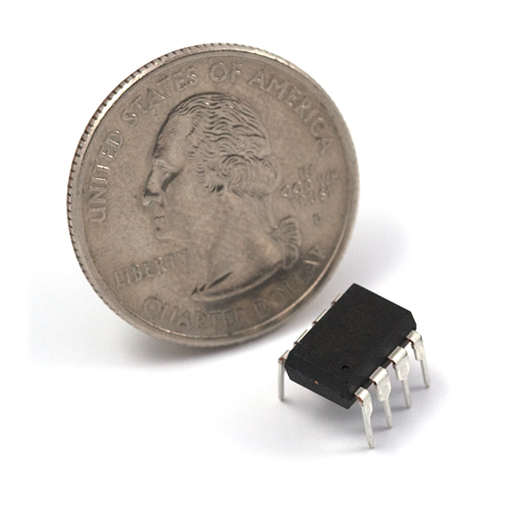
I was envisioning something more or less this size:
I suppose you could get a smaller package, but, seriously, what do you even need for a small homebrew project? You could even power LEDs directly from the output pins if you use an appropriate current-limiting resistor.
Note: if you want your timing to be really accurate, rather than within however many percent, then you will need to calibrate the internal RC oscillator and keep the voltage and temperature fixed, or use an external temperature-stable oscillator, or at least a crystal or a ceramic resonator. I mention this because you want to know exactly how much time elapses between two triggers.
You are building a finite state machine with five stable states, so three D flip-flops are needed. For simplicity assume a Moore state machine where the output is also the current state. Let’s define the current state as three bits: {count enable, green LED on, red LED on}. For example, state 110 would have the counter enabled, the green LED on, and the red LED off. Also define A as trigger A (active high) and B as trigger B (also active high).
Start in state 000 - both LEDs off, counter disabled. Conveniently a reset on the flip-flops will put you in this state (you wanted a manual reset).
State 000:
Next state=000 if AB=00 (stay in the reset state until a trigger is received)
Next state=110 if AB=10 (counter enabled, green LED on)
Next state=101 if AB=01 (counter enabled, red LED on)
Next state=000 if AB=11 (ignore simultaneous triggers)
State 110:
Next state=110 if AB=x0 (stay in current state if no trigger B)
Next state=010 if AB=x1 (counter disabled, green LED on)
State 101:
Next state=101 if AB=x0 (stay in current state if no trigger A)
Next state=001 if AB=x1 (counter disabled, red LED on)
State 101: Next state = 010 (stay in current state until reset)
State 001: Next state = 001 (stay in current state until reset)
How you implement the state machine is up to you. I agree with the previous posters who suggest a microcontroller. You could also use a CPLD, PAL, FPGA, or discrete logic, but in those cases you will have to design the next-state logic by hand or learn Verilog programming.
I can’t even focus my mind on doing this at the component level. The very image of an Arduino board replaces any logical diagram I try to form. Even if for some reason you would want a minimal construction of the most basic parts you still want to make a prototype using a microcontroller.
I only mention the Arduino because I have one sitting around doing nothing, I don’t know what the hottest microtricorder is right now, but if I were spending money I’d aim at something like a Raspberry Pi or better and go through the curve on that so I’m ready for the next thing I want to make. Then if you really need that thing made at the component level you could gig it out for less than you’ll end up paying to get all the parts you’ll need.
A Pi is terrible for a lot of reasons, not least because there’s no way to get accurate timing out of them. The OS takes control at inopportune times and does stuff for milliseconds.
Arduinos are great for prototypes though, because they take out a lot of the hassle. They’d still be ridiculous if you were building thousands of units, but for one-shot stuff they’re a great little package. The OP is concerned about the learning curve, which is much more painful for bare microcontrollers than for packaged ones like Arduino.
Make sure you turn off the default timer interrupts, though.
My picture was of a ATtiny85/45/25. Even that may be overkill for this project, who knows, but they are small and cost $1 and you can use the Arduino IDE to program them in C++. You still need to know how to set up the timers/interrupts/hardware registers of course. You can use your Arduino to flash them.
Well naturally you would use an appropriate real-time operating system or patched Linux, not whatever the Pi comes with out of the box. I remember getting OK latencies with Xenomai even on a single-core Pi 1.
Thanks Marvin. I will try and sort that out.
A design issue is also that it needs to be small and powered by a 9 V battery. I also was worried about my using a micro, without detailed knowledge of what hidden things might throw off timing. The timing range of interest is 350 microseconds. With 50 microseconds range being within the specs we want.
The terrible wide range of signal input voltages is also a problem I am trying to sort out. Needs to be idiot proof.
Use a comparator to clean up your input signals.
50 microseconds is forever to a micro controller. If you interrupt on each signal, you should be able to get your jitter down to under 1 microsecond, even if you are programming in C.