For a little DSP project I’m playing with, I need to perform a frequency detection on a real-valued signal. Specifically, I need to tell whether I’m hearing a 1200 Hz or 2200 Hz tone (maybe some of you can guess what I’m demodulating).
It’s a trivial thing to do on a complex signal with only positive frequencies: you simply take the phase difference between one sample and the next and scale appropriately. But a real signal is an equal sum of positive and negative frequencies and renders this strategy useless.
I know that PLLs can do this, but I’ve always found them fiddly. And I need to acquire the frequency in much less than one wavelength. In my experience, PLLs generally take much longer to lock on.
I have come up with a solution that works. I downconvert the signal by 1700 Hz, putting the desired 1200/2200 Hz signal at -500/500 Hz. The unwanted -2200/-1200 Hz signal is sent down to -3900/-2900 Hz. I then do a simple low-pass filter at about 600 Hz, eliminating the unwanted negative frequencies. Finally, I just check if the phase is going positive or negative to see which frequency I have.
This actually works pretty well, but it seems… complicated. Is there some way to get rid of the negative frequencies without an expensive filter? Or some other way to accomplish what I want more easily?
Hmm… 1200 and 2200 Hz… I’m thinking either you are emulating an old modem for some odd reason, you’re dealing with Caller ID signals, or you’re trying to pick up HART signals on a 4-20 loop.
How clean is your signal? A much simpler method is to measure the time between zero crossings. That method can get fooled if there’s a lot of noise in the signal, but in my experience it takes quite a bit of noise to really muck it up. A little bit of filtering outside of the usable frequency range helps clean things up a bit too.
A bit more complicated method, but one you might be able to find a library for with your DSP which might make it easy, is to do a FFT on the incoming signal. It’s more complicated than a zero crossing detect, but less complicated than your method, I think. There are some simplified versions of FFTs that work pretty well for FSK type signals.
Yep! Specifically, I’m decoding APRS (Automatic Position Reporting System) signals, which use the Bell 202 modem standard. As do the other examples you mentioned.
It’s sort of a weird setup. It’s a frequency-modulated signal (FSK) running on a frequency-modulated channel (narrowband FM).
I thought about that, but I think the real trouble is that it’s a 1200 bps signal on a 1200 Hz tone. So depending on the phase I might only get a single good crossing. Based on inspecting the signal by hand, that technique is unfortunately a no-go.
Right now I’m using a clean local source, but in the future I’ll be trying to receive more distant transmissions and they’ll have more noise.
Hmm. I rejected this early on due to the cost of the FFT, but… the frequencies are far enough apart that I only need a handful of samples. Depending on the sample rate, I could get away with perhaps 8 or 16 samples, and that’s cheap, especially starting with real values. I’ll look into this–thanks!
BTW, the DSP code is running on a PC, so I’m not too limited in math power. Still, I don’t want to use more than I have to. I think I still have some headroom in the current setup (my filter is probably overkill, and I might be able to switch from FIR to IIR), but I’m not sure what the minimum is.
I once wrote assembly code for a Microchip PIC16c84 microcontrller that could decode DTMF signals using DFT (discrete fourier transform). The analog signal was wired to a DIGITAL input, making a 1-bit analog to digital converter. It worked suprisingly well.
It’s neat stuff. It’s funny how this old-school technology continues to be integrated into more modern equipment. The Bell 202 standard was created in 1980. Now, I’m generating packets with my phone. The phone uses GPS for the position, and easily has enough horsepower to synthesize the packet and send it out the audio jack.
For reception, I’m using cheap SDR USB dongles with my PC. No need for specialized equipment.
Now I just need to get my ham license (the test is easy enough; I just need to go and do it).
Cool! I cut my microcontroller teeth with PICs. They aren’t exactly high powered devices, so I’m impressed that you got your DFT code to be that efficient.
I’ve also found that 1-bit inputs work surprisingly well. If the source is too high power and AGC is disabled, these SDR dongles can easily be clamped to just 0 or 1. Most of the time, my stuff works anyway. Most of the extra signal energy is in frequencies you don’t care about and probably get filtered away.
You can do two simple low cpu power filters…
You therefore don’t need to determine frequency up front.
and You don’t need AGC.
But if you want to do it more simply, then just count swings …
is sample 2 the opposite of sample 1 ? (+v to -ve or -ve to +ve …stated in terms of radio signal received at the antenna… ) … well just compare for sign change… And repeat for 3 compared to 2, and then for 4 compared to 3… etc, …
So you count the swings…
These counts then indicate frequency…won’t 2200 give nearly twice as many swings ?
Some interesting stuff in that link–thanks. In particular, the paper it links to.
The paper confirms my suspicion that the edge detection method isn’t quite good enough here and that some kind of filter is needed.
It actually uses four filters–for each frequency, there’s an in-phase and quadrature filter. Effectively this means that one filter has a phase delay of X and the other by X+90 degrees. It then compares the magnitude (i[sup]2[/sup] + q[sup]2[/sup]) of each pair, which gives the energy in the signal (which is always positive and constant for a perfect sinusoid). It compares the energy for each frequency and picks a winner.
Neat. My current filter builder doesn’t currently support filters with a specific phase delay like that, but it’s clearly a useful technique.
Just popping in to apply some light pressure. Go get licensed. GO!
With the project you’re describing, I’ll bet you pass Tech and General without even trying.
As I recall, the fact that the input was only one bit greatly simplified the math. Now you made me go dig out the source code. A comment in some basic code I wrote to test the algorithm says “NOTE: this IS NOT a general DFT algorithm. The input signal X(N) is assumed to have values of only 1 or 0”
Thanks for the encouragement! I took some tech sample tests online and can pass them without breaking a sweat. Not sure about general yet; I suspect I need a bit of studying for that. To be honest, the only thing that’s stopped me so far is that all the exams are either >60 miles away or at 8 am. I’m a bit lazy, so I’ve been waiting for something closer and later!
Makes sense. A DFT can be expressed as a matrix multiply, where the coefficients are powers of e[sup]-i2pi/N[/sup]. If the input data is all zeroes and ones, these just turn into conditional adds. Or a bitwise and, if you want–if the input data is 0x00 or 0xff, you can just do: (X[0] & W[0]) + (X[1] & W[1]) + … Bitwise ops are generally cheap on microcontrollers (multiplies, not so much).
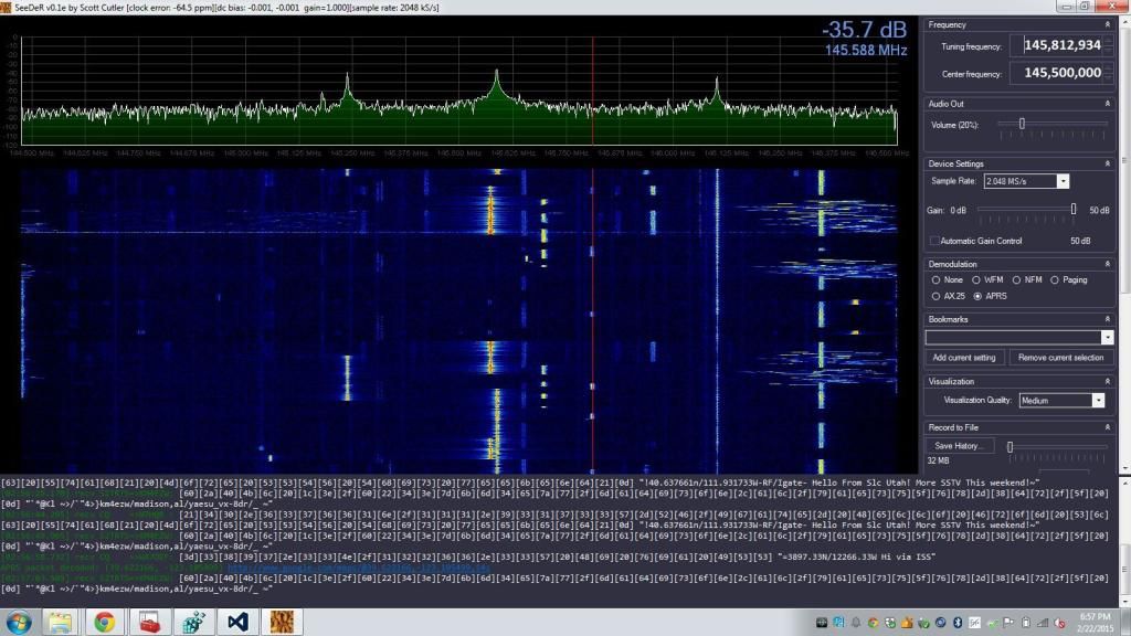
My decoding software works great. When I mentioned “more distant transmissions” before, what I really meant was “from space.” The International Space Station has an APRS repeater on it for amateur use. And tonight, I decoded some packets from it!
For equipment, all I used was a salvage 3-element Yagi and an $8 SDR dongle. A friend pointed the Yagi vaguely in the right direction. Software did the rest.
I wonder what my homeowner’s association would say about me mounting a big 2 M omni antenna on my balcony…