The most basic carburetor, typically found on a gasoline-powered lawn mower, is pretty darn simple:
-
Fuel from the tank flows (or is pumped) into a float bowl. When the float bowl is full, a float rises up and shuts a cute little valve, preventing any more fuel from entering the bowl. If the bowl is less than full, the float drops, opens the valve, and lets more fuel in.
-
During an intake stroke, air is drawn through a venturi, creating a pressure drop that sips fuel from a straw in the bowl and mixes it with that intake air. Mixture is drawn in to the combustion chamber, and your grass gets cut.
These work nicely, as long as they’re operated on approximately level ground. The float bowl depends on gravity for its operation, so if you get to really off-kilter angles, they don’t run so well.
This is why things like string trimmers and chainsaws use diaphragm carburetors instead. They are pretty much immune to gravity, so you can run a chainsaw right side up, upside down, sideways, whatever, it just doesn’t care.
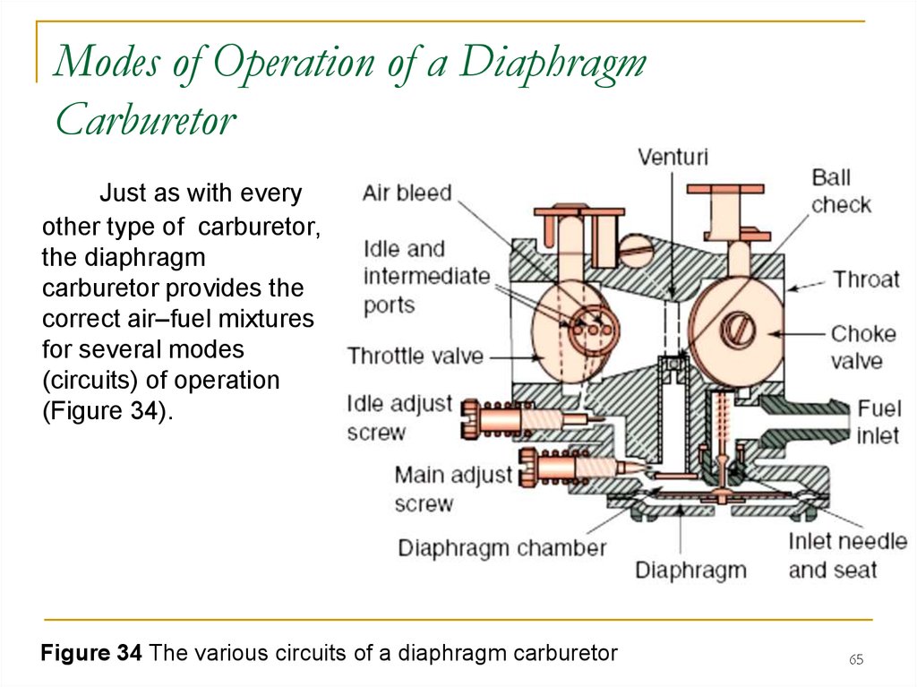
So now I’m trying to understand how a diaphragm carburetor works. I’ve been watching this guy’s video, which shows a schematic cross-section of a diaphragm carb:
")
To help orient you, the long black thing angling up/left from bottom right is the throttle valve, shown wide-open with air moving away from your eyeballs through the venturi in the middle.
I understand the diaphragm pump at the bottom of the carb well enough: crankcase pressure pulses actuate the small diaphragm at bottom-center, which - together with a couple of one-way flapper valves - moves fuel from the tank up toward the metering valve at top left. He describes all of this from about 1:20 to 4:30.
The part I’m struggling to get my head around starts at 4:31. This is where he starts talking about fuel being metered into the venturi. At this point, the piston is on the upstroke, drawing air through the venturi and creating a vacuum on the large metering diaphragm at the top. The little nubbin on the center of the diaphragm pushes the lever to lift the metering needle (at top left) off of its seat. There’s vacuum under the diaphragm because of the air flow through the venturi, so it should pull fuel up past that metering valve, right?
Except how can it do that? The chamber just upstream of the metering valve is sealed by those checkvalves, drawn tight against their seats by the crankcase vacuum pulling on the pumping diaphragm at the bottom. It’s like trying to suck water out of a steel tube that’s been capped at the other end.
The other part of my confusion is that the the diaphragm pump ends up trying to push fuel downstream against the closed metering valve, so how can it actually move any fuel along at all?
The only way I can imagine this thing working is this:
-
During an intake stroke, crankcase vacuum is creating a vacuum under the pumping diaphragm, closing the checkvalve at bottom right.
-
However, venturi vacuum is even greater than crankcase vacuum. So when the metering valve at top left opens, that venturi vacuum is strong enough to defeat the pumping diaphragm vacuum, opening that checkvalve at bottom right and pulling fuel through the carb to the venturi from all the way back in the tank.
If I’m correctly understanding how a diaphragm carb works during an intake stroke, then I don’t understand why the pumping section is needed at all. The venturi vacuum seems like it can pull all the fuel it needs straight from the tank, and it seems like the pump diaphragm isn’t actually allowed to do anything useful, since its outstroke is only ever pushing fuel against a closed metering valve. It seems likely that I’m misunderstanding, since diaphragm carbs continue to be made with a pumping section. So…help me understand?