Looking at the M6 sized earth bolt in my 4wd engine bay where there are accessory cable lugs bolted under the head of bolt, and I presume the current flows through the underside of bolt to outer thread of body.
I also ask as most bolts are at least mild steel or even high tensile & may not be very conductive?
The primary current path is between the lug and the thing it is bolted to. While the bolt probably does carry some current, it is not necessary for it to do so.
I designed a motor control board that uses 5mm studs. The motor leads are bolted to the PCB through a ring terminal. This connection will easily handle 100A.
Electric golf carts can supply 5-600 amps through 3/8" (9mm) connections. In this case all of the clamping surfaces are bare metal, though. A slightly loose connection can melt the top of the battery where the terminal is molded into the lead. This is a fairly common topic on the cart forums.
They do use brass nuts but despite what many people think, brass is not all that great of a conductor either. The slightest amount of alloying metal in copper reduces its conductivity which is why good quality wire is only made from virgin copper, never recycled. I use copper washers and oversized beryllium copper nuts.
The ground connections in a car only carry what current is being drawn by that circuit, so not really all that much. The big load is the starter at several hundred amps but that grounds through the starter body.
The medium-sized loads are (were) big driving lights. And they also are (were) often separately earthed.
The “current carrying ability” of a normal circuit is set by how hot you allow it it get. Short bolts bolted to steel structural elements can carry lots of current before they get hot: You can get an idea of how much from arc-welding sets, which use 100’s of amps, have negligible loss in the structural iron (all the heat is in the arc), but have expensive copper cables (because even negligible loss isn’t negligible when you have a long cable run)
Although welding uses 100 Amps commonly, you wouldn’t want that to run through an actual building. You can get corrosion, metal migration, and softening, even when you don’t have any fire hazard.
You also get voltage drops on long runs and bad joints. A normal car battery has a couple of volts variation anyway, so apart from the starter motor, nothing in a car is sensitive to voltage loss anyway.
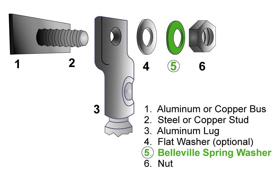
Here is a drawing of a lug (3) bolted to a bus (1). A wire, which is shown but not annotated in the drawing, connects to the bottom of the lug. The wire is secured in the lug via a crimp, compression screw, or solder. The primary current path is from the wire, to the lug, and then to the bus.
In a vehicle, the lug will not be bolted to a bus. It will instead be bolted to the engine, frame, or body.
As can be seen in the drawing, there is nothing between the lug and bus; the lug makes direct contact with the bus. This is important, since you want to minimize the contact resistance between the lug and bus.
Will there be current through the stud (2)? Yea, probably. After all, it is in parallel with the primary current path. But the design of a bolted junction will assume all the current flows directly from the stud to the bus. Any current that flows in the stud is nice, but not necessary.
There’s a lot of literature out there on how to properly make a bolted electrical joint. It’s more technical that what you might think… there’s material selection, surface finishes, cleanliness, anti-oxidation compound, wet/dry torque values, etc. I won’t get in to all of that, but suffice to say there’s more to it than simply slapping a lug onto a stud and tightening it with your Craftsman ratchet & socket.
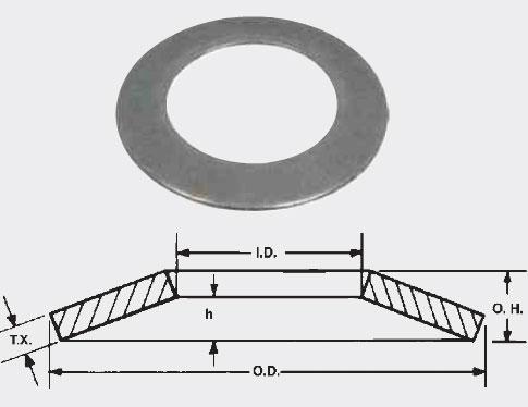
I specify that Belleville washers be used to provide uniform pressure on the lug. We have never had a failure due to this connection, after many thousands of boards shipped.
That is certainly true for a buss. But lots of automotive ground connections are just a sheet metal screw into the painted body work. They depend totally on the current passing through the screw which is in intimate contact with the body. Larger ground points use the frame and are much better. They may even have a bare metal pad around the attachment point.
In my case the earth bolt with an E on it sits over the wheel arch area & the surrounding area is painted, so The current has to go through the bolt & thread of body etc. The negative of starter battery also is bolted to this point, however the cable also goes onwards presumably to the alternator, perhaps?
Also if grounding say spotlights somewhere else, wouldn’t that same current go through the earth bolt in the end?
Only if you wanted it too. I’ve only got two connections on the negative side of my battery: But each wire goes straight to another junction point, and several things are directly connected at each junction point, not just through a stud.
There will be multiple routes for ground, so not necessarily. That cable goes onward to the engine block which will have at least two grounding straps that also connect it to the body, even if it’s unscrewed, you would only lose ground to anything else directly grounded there, the alternative path would be the the body, to the engine, and on through the wire anyhow…
100 amps in a 12 volt system ( actual 13.2-13.5v) is pretty safe to assume.
Also pretty safe to assume your alternator is capable of less than that at maximum.
But how can my battery be rated 450 550 600+ cranking amps?
The wire can hold that, momentarily.
As was mentioned earlier, it’s about heat and heat takes time. 10ga stranded wire can hold 100amps at 13-14v indefinitely.