Is there a stronger profile than a cone ?

Imagine a metal truncated cone, ( I believe “frustum” is the mathematical term) spun on a lathe from sheet metal. The top of the cone is solid, continuous, not hollow. The wide end, the base, is of course open.

If you place this cone on a flat surface and apply increasing pressure vertically downwards to the top, obviously there will come a point at which the cone will start to buckle and deform.

My question is whether there is a stronger profile than a straight conic profile … if the metal were spun with a concave profile to somewhat resemble the mouth of a trumpet, for example, would this have more resistance to deformation ?

Or perhaps a convex “parabolic” type profile would be stronger?

My suspicion is that for any given top diameter and base diameter there is in fact an optimum curve which offers maximum resistance , and that there is a mathematical formula to describe that curve, although what that formula might be I have not the faintest idea.

For the purposes of discussion let us assume arbitarily that the height of the truncated cone is equal to the diameter of the base … and that the diameter of the top is no larger than 1/2 the diameter of the base. ( I do get that the closer a cone approximates to a cylinder, the stronger it will become.)

More complicated shapes can be stronger. A ripply cone, for instance. Perhaps you are asking about high points in the compromise between strong and complicated.

\yes, I appreciate that subsequent “embossing” can add to the strength, but I was more concerned with the original curve (as it would come off the lathe).

Thinking about it a bit further, my common sense instinct tells me that maybe the cone is in fact the strongest shape, as it minimizes the distance over which the force is distributed, compared to any curve, which by definition would increase the distance and the area over which the force would be distributed.

That’s just gut feeling, however, the math might say different.

My guess is something more like parabolic curve than a straight line.

I suspect an oval (elliptical? parabolic?) dome would be stronger. You don’t see very many buildings with unsupported cone-shaped roofs.

…nm

If it’s only a vertical load I think it will be convex with the profile of an arch. Parabolic or catenary curve I think. It would be a cylinder if the flat top wasn’t subject to buckling.

How is the load distributed? If the load is all at one point, then the shape supporting it ought to have a cusp at that point (i.e., it’d locally be shaped like the point of a cone). I’m pretty sure, though, that you’d want to curve it like a dome of some sort below that

As the base is larger than the apex, (and the shell is not loaded by self-weight), the stess on the shell wall is lower at the bottom than at the top.

This means that you can either make the bottom rim thinner, or you may bell-out the bottom to cover a wider area (giving the modern “spire” shape). The buckling equation for cones includes both a thickness squared term and and cosine squared term.

However, the shell must be supported at the bottom or it will fail in tension. (A different kind of failure). If there are no foundations, nor a steel cable around the base of the dome (as in St Pauls Cathedral, London), then you must thicken up the bottom rim.

(In practice, the simple buckling equations for cones aren’t very good, and don’t take account of lots of real world situations)

Roofs aren’t dealing with the same issues as the metal cone: self-loading is important for a roof, wheras the weight of the cone is going to be minimal compared to the weight it supports. More importantly brick and stone (particularly when you include the joints) are very strong in compression, but much worse for tension and shear forces, so the best design is more arch-shaped (often with iron cables or chains added going around).
But solid metal is pretty good in tension, even stronger than in compression, and shear is good too, so the strongest shape probably isn’t exactly the same as for a brick or concrete roof (even a steel-reinforced brick roof).

Now it’s not completely clear what ‘stronger’ means in the OP, but I’ll guess it’s best ratio of weight supported to mass of the cone?

My mostly WAG is that the optimum would be close to cone shaped, but with varying thickness of the walls – thicker at the top (since there’s less area to distribute the vertical force over), with a beefy band around the bottom to keep the bottom from splaying out. (Or, what Melbourne said)

Just guessing from the fact that you don’t see triangular arches, I would expect that a section of a dome would be stronger. Maybe a rotated brachistochrone would be best (just a WAG).

You don’t see triangular arches because the base of the arch would direct almost all the weight of the arch and whatever it supports horizontally. So the walls the arch sits on would be slowly pushed apart. If horizontal loading of the supporting structure wasn’t a problem, triangular arches would be fine. In fact, an equilateral triangle is the strongest load bearing shape of all since it won’t deform.

There were triangular arches, solid ones though.

Why a cone? In terms of forces, and neglecting the support’s own weight, it really should not matter if the cone was pointed upwards or downwards, It is jsut resisting a crushing force between 2 surfaces. A cylinder I would think should be stronger (and the flatter the batter), perhaps bowed out or perhaps even in. I don’t know why you would want to make it cone shaped as that seems it would compromise the strength in the cylinder but the trade off would be a more stable support on one size.

If you’re thinking of an homogeneous material with only vertical loading I think a cylinder would have the highest strength/weight ratio for a given volume of material. A cone or curved wall shape may resist buckling better if there is any twisting.

Some bicycles use “double butted” tubing that is thick walled at the ends and thinner at mid-length for light weight plus resistant to buckling.

The flatter the cone gets, the more prone it is to failure. When the cone is flat, it takes an infinite amount of force sideways to keep it from collapsing.

This is the inverted case of a string supporting a weight: it would take an infinite amount of tension to prevent the string sagging when you hang a weight on it.

The optimum shape, for a weightless string, is shown by the shape a string takes when you hang a weight on it. Note that the string is held firmly at the ends. Rotate this through 180 degrees, invert it, and you have the optimum shape for supporting a point weight on a fixed foundation.

At some point, the structure will fail. If it is weightless and perfect, it will fail in shear or compression at the point, where the stress is greatest. In practice, a minimum cost thin shell made out of an engineering material (metal, stone, whatever) will fail by buckling before it fails in compression/shear.

The buckling equation includes the angle of the cone (actually, the square of the cosine of the angle). The steeper the cone, the stronger the structure, because, as with the string, when you flatten out the cone you must increase the sidways stress by a whole lot to get the stress vector to point along the direction of the surface. So a flat cone has much much more stress than a steep cone.

At the limit, the strongest cone is the simple cylinder (which is part of why we use columns not cones to hold up roofs). But then, how big a cylinder? Because the whole cylinder will buckle (bend) if it is too thin, and if it is too thin it will fail in compression/shear, and if it is too thin it might just fall over, and perhaps you actually want some space underneath anyway?

Back to the string: strongest straight up and down, but your picture will swing back and forth if it dangles straight down from a string, and you don’t want staples in the middle of the picture either. So you fix the ends of the wire to the frame, and the wire forms a triangle when it hangs from the picture hook.

As several have said, if we consider strength to compressional load bearing ratio as the indication of ‘best’, a cylinder is the best form to use. Certainly cylinders can have torsional load issues and buckling can set in pretty quickly, and catastrophically, if you just nudge over certain criteria but in structures that support big axial loads, these can generally be dealt with through multiple cylinders and cross bracing.

Now if we need a single column, no cross bracing allowed , and we have to carry a metric arseload of weight, what do you do?

You use a cylinder of large enough diameter and suitable wall thickness that can manage the axial ( including buckling) and expected torsional loads

Here is the Draugen platform, single big cylinder supporting a lot of weight.

Imgur

(I have no idea whose Flickr account this is , but google image search came up with it and it illustrates the point)

You can see at the top part ( close to the water) of the supporting column, is a straight tube, made of concrete, it flares out into an inverted cone where it meets the bottom of the topside. This flare out is to manage the stresses transferring from the epic ass load of top side equipment , into the straight concrete tube. Ok there are some other concerns , such as ringing caused by waves slamming into the structure, and managing and dispersing that energy smoothly goes into this design a little bit. That said the main purpose of a curved profile is to be able to manage loads in material (concrete) that is strong in compression, but weak in shear. In that picture you can see huge loads hanging out to the side, supported by steel which is good in shear and compression and tension, but once they transition to concrete , they have those smooth curves trying to manage the whole shear / compressional loading.

Now if we look under water you will see that column rapidly flares back out again ( once again google found this image)

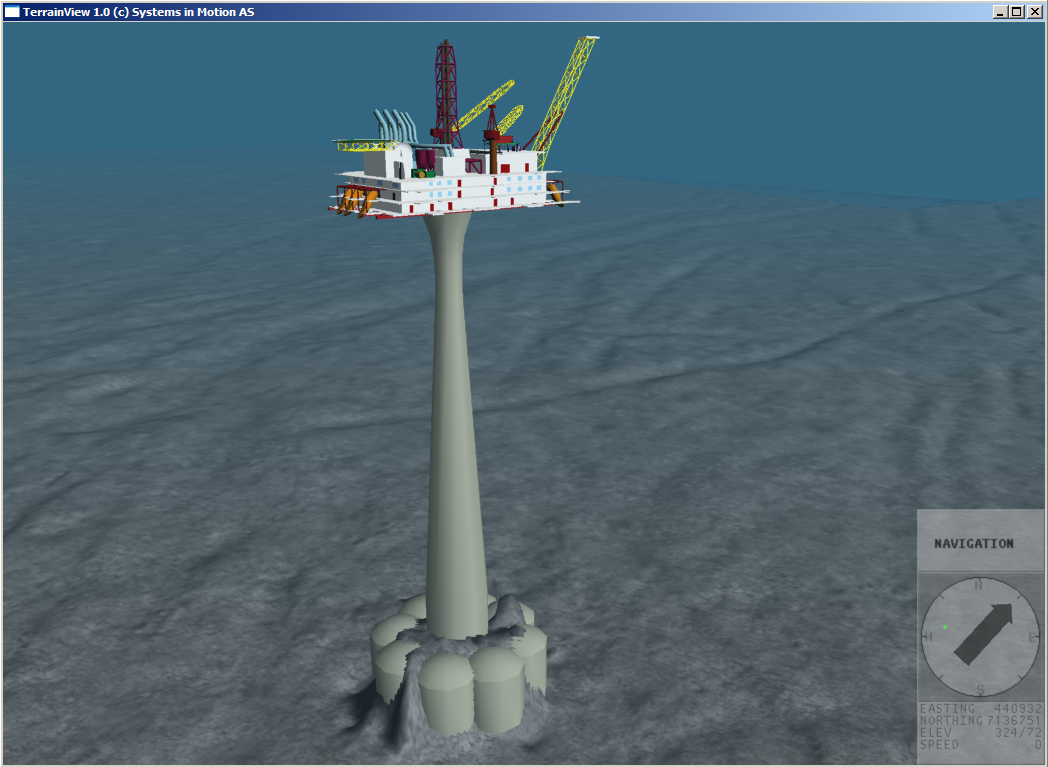
Here the issue is not so much that the cone is a better shape than a cylinder for axial load bearing, but that the tube, made of concrete has to support the load above which is rising as we get deeper. The cylinder has to get fatter to support the ever increasing load of the weight of the increasing length of support structure above it. Once again in this case, as concrete is great in compression and sucks in shear, and generally to manage smooth stress transitions, they flare it out in a cone. The exact profile of the flare out is really a fine tuning of amount of material and expected load distribution. They also have to deal with trying to distribute the loads over a large surface area, so like at the topside, they flare out to manage the stress transitions.

So, for a given strength to weight ratio for compressional loads, a cylinder is better than a cone. When you have real world conditions and have to compromise on strength to weight , such as dealing with stress transitions, shear vs compressional load bearing and the ever increasing weight of the supporting structure above you, you end up with a cone. And a cone is just a series of stacked different sized cylinders :wink:

Probably an egg shape.

AANEngineer, but your example has a much bigger problem than the vertical load to deal with. Anyone who has tried to stand up in moving water will have some idea of the immense forces that are acting at 90 degrees to the platform support. Wind acting on the superstructure is far from trivial either.

The support cylinder flares at the bottom to resist the shear forces, not the compression. If the force is perpendicular to the column, a cylinder will be the strongest shape.

The supporting structure shown is a cantilevered beam-column with significant lateral loading near the top end, due to wind, wave, and seismic forces. It flares at the top to distribute the vertical reaction over a larger area, but it flares at the bottom to resist the bending moment, which increases to a maximum at the fixed end (the bottom). The bending moment causes both compressive and tensile stresses. The concrete is well suited to resist the compression, and steel reinforcing bars are embedded in the concrete to resist the tension. The increased cross-section at the bottom would help with the shear forces, but I doubt those would control the design.