I work for a company that makes model boat steam plants. Advising potential customers on the appropiate size & # of blades propeller, is matched to the steam and model boat of their choice. I can find lots of material for large ship propeller design but my experience is that my model boat market does not “proportionally size down” to the model boat market.
I would appreciate advice on how to calculate potential rotational speed vs thrust curve from the normally advertised diameter and pitch information on offer in the market.
A good place to start is the model airplane prop curves. Especially the information posted by the University of Illinois.
There’s a lot of variables. First is pitch definition. Is it based on the zero lift angle of the prop section or the angle formed by a line along the bottom of the section. Few manufacturers have/can/will provide accurate data.
What you need is an efficiency number and you may have to measure that. The scope of the project is beyond a thread response. Probably need a PM. I have been thinking of making measurement fixtures for this problem and I might be able to assist you.
Depends what you mean by “proportionally size down”. Dimensional analysis is one of the first things you would do to characterize a propeller, resulting in parameters like the thrust coefficient, torque coefficient, efficiency, and power coefficient in terms of parameters like the advance ratio and blade angle. For example, look at the graphs at the bottom of this page describing “typical” propeller performance for aeroplanes, as described by @Crane.
The question is if you can find published data that are more or less applicable to your model boats, or possibly make your own calculations. In all cases you may have to measure something, just to check you have it right.
see if this helps:
there are propeller curves for some standard marine propeller series
example:
Great reference
Nice family of curves. Measure hull resistance then measure a couple of speed/rpm points and you should be able to match some point on the curves.
Fluid dynamics are complicated enough that it’s likely that you’ll have to just run the experiments yourself to find out. Or at least, that’ll be easier than trying to do the calculations from first principles.
One of the problems with scale models is that lots of things don’t scale linearly, and speed expectations is one of them.
Take a model liner. Titanic is a good start. The real ship would cruise at 21 knots. That is roughly 10 meters per second. It would travel its own length in about 25 seconds.
A one meter long scale model would be a very disappointing sight travelling so slowly it took 25 seconds to travel one metre. That is perhaps an extreme, but one reason scale model propellers don’t work out in practice.
Given the huge scale differences I would assume that the fluid flow regimes may be significantly different. Reynolds number is going to be much lower. Maybe that matters. Would be interesting to know.
Hi Crane
Not sure what you mean about a PM! Are you suggesting a direct 1 in 1 discussion. If so I’m agreeable. Email stuartrowe@lizzy.com.au.
Stuart
Hi Chronos
I do in fact have a test setup close to construction for this purpose. It’s built to a budget but I am hoping to get enough useful information to justify refining the design - and hopefully get model boat enthusiasts interested in finding out how to improve the performance of their boats.
Please advise if you would like to be kept updated on my progress.
Kind regards
Stuart
Hi Francis_Vaughan
You are quite correct about the difficulties of scaling complex environments.
As you will read in my replies to others I’m going to continue with building my own test rig for my sized propellers.
Thanks for your contribution.
Kind regards
Stuart
Hi Crane
Any suggestions as to how to “measure hull resistance” ? I have a few other things to do in this epic just now but this is not a priority - but I would love to hear your suggestions. I’ll have to deal with it eventually.
Thanks for responding,
Kind regards
Stuart
Hi DPRX,
Wow - this looks like the sort of chart I can expect to develop.
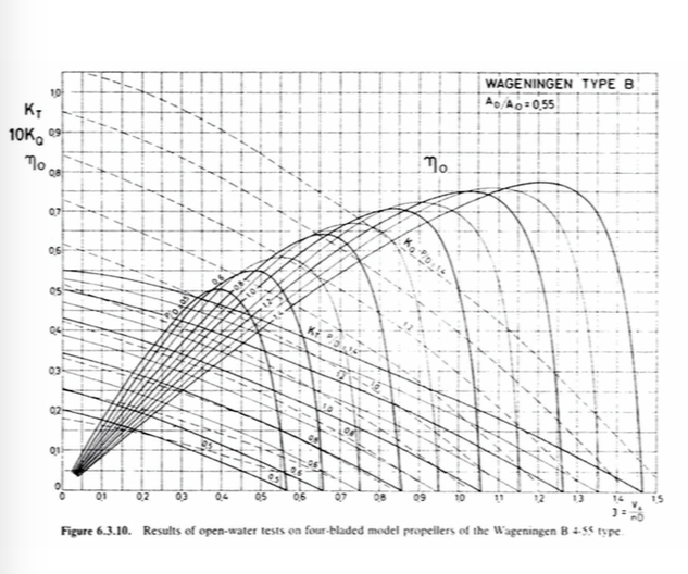
What are the axis’s definitions please.
Is this part of a library that I could view for other propeller types?
Is there a drawing of a testing structure used?
More information please.
Thanks for responding.
Kind regards
Stuart
Many thanks for responding. I am a retired mechanical engineer and my recollection of design functions of anything mechanical is dated. Thus I will duck out on the heavy duty calculation functions I think you are proposing and continue to develop my original test bed as mentioned in other responses.
Kind regards
Stuart
The diagrams themselves only graph dimensionless quantities, but the book does say, concerning model testing, that
Open-water tests at which the propeller axis height below the water surface was varied have shown that noticeable surface waves will no longer occur if the distance from the axis to the water surface is equal to or greater than the propeller diameter. In such cases Froude’s law can be neglected. Furthermore, it is almost impracticable to comply with Reynolds’ law, but care should be taken, by an appropriate selection of the model scale and rate of revolutions, that the Reynolds number does not fall below certain critical values. Generally, the diameter of the model propeller should not be less than 200 mm. The influence of laminar flow phenomena will then be minimized.
There is discussion of correction for Reynolds number effects, and there is a whole chapter on model<->ship correlation, so apparently it does matter.
J = \dfrac{V_A}{nD} where V_A is the speed of advance, n is the rate of revolution, and D is the diameter of the propeller. Plotted on the vertical axis are the thrust coefficient K_T = \dfrac{T}{\rho n^2D^4} where T = thrust, \rho the fluid density; the torque coefficient K_Q=\dfrac{Q}{\rho n^2 D^5}, Q = torque; and the propeller efficiency in open water \eta_O = \dfrac{K_T}{K_Q}\dfrac{J}{2\pi}. P/D is the pitch ratio and A_D/A_O the blade area ratio.
The book contains drawings of the models and propellers used and of all the experimental set-ups, and how to build up the diagrams. There are a bunch of different sample diagrams, but not a dedicated library of test results for every conceivable type of commercially available propeller—wouldn’t much of that be available from the manufacturer?
By heavy-duty calculation, there is also the possibility of finding some open-source CFD code and letting the computer figure everything out via simulation. Perhaps others could tell you more about that possibility and which code/software you might use. Otherwise, Harvald’s book explains everything about how to model and test ship resistance and propulsion.
PM is a private message. I sent you one. I’ll get off an email.
A test is worth ten thousand opinions.
When scaling things like this, we try to keep relevant fluid flow dimensionless numbers in the same vicinity. (When no actual scaling data is available)
For this kind of flow, the Reynolds’s Number and the Power Number comes to mind.
Taylor number maybe important too.
No email yet. Try again please
You’ll find me at stuartrowe@lizzy.com.au or on request for relay to info@miniaturesteammodels.com
Sorry I’ve had distractions. Will do it today!
Did you get it?