I was recently contracted to do a Hardware / Firmware design for a radio-controlled traffic sign. I finished the job, tested it, and it worked perfectly. I packed up three boards and sent them to the customer, and was surprised when he called me a few days later and said it wasn’t working correctly. The sign uses 3 commercial LED traffic flasher modules (they internally generate the correct flash pattern, and sync to other modules so that all of them flash in the right sequence). When he tried one module, it worked correctly, but as soon as he added another one, it failed. The failure mode was that it would “try” to flash, but then reset and start from idle. I talked him through a few ideas, but nothing worked, so I asked him to send it all back to me.
I set up the sign on my bench and tested it, and - it failed. Which was actually a good thing, since if it worked for me, and not for him, it would have been a bear to figure out. My first thought was that there was some sort of RFI caused by the three LEDs, or maybe those in combination with the radio antenna, but I put the antenna in a cable, and that didn’t change anything. When I was talking to him on the phone, it seemed that moving the circuit board away from the metal backplane might have helped the problem, but I tried that, and there was no change. I put my meter on the input voltage (which was being supplied by a beefy 36Ah 12v battery), and I could see the barest of blips when I tried to make the sign flash. So, I knew that had to be the issue, but I couldn’t understand why it had worked so well for me at the design stage. I put a big capacitor across the power inputs to the board, and the problem went away.
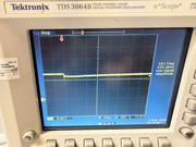
I started to write up my findings, letting him know that i had fixed the issue, but that I still wasn’t sure what was actually causing it, when the light bulb (maybe LED) went on. He had added DC circuit breakers from the battery. I hadn’t thought much about them. After all, they are just a switch, right? Wrong. It dawned on me that they must have some Brobdingnagian inductance in order to trip the breaker at the low currents we were using. Sure enough, I scoped the voltage at the input to the board, and it went to zero when the LEDs were switched on, then sloped up in a perfect linear fashion until the regulator started to conduct again. I made measurements at various capacitances, and decided that 1,000µF would be more than enough to eliminate the problem even if they went to much more powerful flashers.
No additional input capacitance:
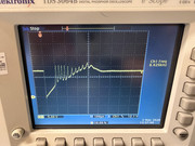
200µF:
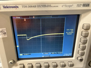
1000µF: