As some of you might know, I’m a volunteer firefighter. With all that fun stuff comes wiring up my car with lights and siren. I have a current system that I’m not very proud of, but gets the job done with relays and a buttload of lamp wire. What I’d like to do it make something that will be much more streamlined, but I need to know what I need to procure (and if you could send me to a reputable website, that’d be much obliged as well)…
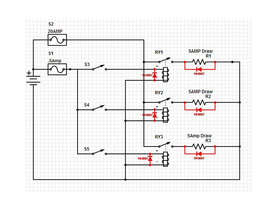
What’s going on is that I have a set of 3 switches inside the vehicle that will control the lightbar, Siren, and the Alternating Headlight assembly. I want to keep the voltage to that assembly to a bare minimum. Then, in the engine compartment, I have 3 relays to switch from little to big power and the each lead goes to each component.
Here’s the schematic (as well as I can do): http://screencast.com/t/6te9Ao9cZ
I’m planning on buying 2 project boxes… 1 for the inside that will have the 3 switches and an rj45 jack. then 1 for under the hood with another rj45 jack and all the outputs and leads to the battery, fuses and the like.
I bring the following skills to the table:
I can solder. I know what a cold solder joint is
I have time to spend
I have a fire extinguisher at my disposal at all times just in case… (:
Hopefully all this makes sense. My questions are :
Am I approaching this correctly with putting all the fuses in the engine compartment area?
is a network cable good enough to connect the inside and outside boxes or should I look for something different?
I did a brief search on automotive relays and project boards and couldn’t find anything that would suit my needs.
Thanks for all your support…
Your schematic looks fine.
If you are ask whether network cable is OK to use to run the “control voltage” for the relays, I would say it is.
You want to put your fuses where they are easy to get at. I would add small LED pilot lights (with appropriate dropping resistors) as blown-fuse indicators. It’s always nice to be able to see if you are getting power.
An RJ-45 isn’t designed for this sort of thing. It’s not going to last very long. My first thought was a Molex connector, as johnpost already suggested. i would probably use something with crimp pins rather than solder. You should be able to find switches and relays with spade contacts so you can crimp on connectors for those as well. I’ll just echo what johnpost said. #18 wire, and there’s no need for project board. Fuses and relays go in the engine compartment, in a sealed box that is out of harm’s way for splashed up water, dirt. etc. Heat shrink tubing around the outside of the connectors will help prevent corrosion of the wire ends and connector pins as well.
One thing about your schematic. You are wiring directly to the battery. This has the advantage that your lights, siren etc. will still work when you shut the vehicle off (if that’s something you need). On the other hand, it also means that if you leave a switch on or if a relay gets sticky when it’s older it will drain the battery and kill it. If you want everything to shut off when you turn the vehicle off you’ll need to find a switched accessory circuit that can handle 20 amps or add another relay that is turned on by the accessory circuit which then powers everything on your schematic.
Use mechanical relays. Don’t use solid state relays, unless you add a mechanical relay that switches the power off when the vehicle is turned off. The reason for this is that solid state relays are never completely on or completely off. They’ll be close enough for your use, except that when you turn everything off there will still be leakage current going through them. It won’t be enough current to turn on the lights or siren, but it will be enough to drain your battery. Powering off of an accessory circuit or adding a mechanical relay to disconnect your circuits when the vehicle is off will prevent this leakage current problem.
Thanks so much… Locking Molex it is… I didn’t even consider that (I’m a computer nerd by trade)… I have a sealed box in the engine compartment and both fuses will be accessible.
My relays are mechanical. So, that’s good.
I went back and forth on tying it to the battery or the ignition. I went with the battery cause I want to make sure I can keep it on during a run (at least the lightbar which will draw little power now that it will be LED [hopefully]). Ok… I appreciate all your insight… I hope to knock this out in a few days.
RJ45’s are commonly used on commercial and public safety mobile radio microphone connectors so they aren’t the Really Horrible idea some are suggesting. Mic cords can be counted on to get pulled, twisted and otherwise abused in ways that lighting controls probably wouldn’t. This does assume a nice molded connector and quality cabling, though, not field crimped solid CAT5.
Not wanting to be a wet blanket, but you might want to at least look at the commercially-available siren/light controllers as they’re already designed for the purpose, and while not exactly plug and play (unless you own something like a Crown Vic with police package, for which almost everything is plug and play), they add some nice features like a PA, wig-wag lights and using the existing steering wheel horn button to control added yelp/phaser sounds.
I’ve known two VFD people who became the unfortuate subjects of fire calls and endless embarrassment when their home-made wiring shorted out. One jeep was a total crispy loss and the other was caught at the “bubbling and charring paint” stage.
On the other hand, this is exactly what you want for the task in hand. A Molex connector should never be used in an application where there is strain on it - that means you have messed up the design of the wiring loom. The high insertion and removal force is a function of the tight fit, and the lack of finger grip is simply because they are only ever intended to be undone very rarely, if ever. What they are is reliable, there are billions of Molex connectors around the planet, and they just work.
OK, not to derail this thread too much more, but I have a lot of experience with Molex connectors. I don’t like them for hobby applications, because hobbyists are generally not aware of their shortcomings. They use crimped contacts, and most people don’t have a proper crimp tool (or don’t know how to use a real crimp tool), which leads to bad connections. This is usually discovered when the user goes to unplug the connecter, and has to use the wire for leverage, since there is no grip area on the connect shell. Then, the bad crimps make themselves known as the wire slides out from the contacts. I always recommend soldering molex contacts after crimping.
Connectors suck. Don’t use one if you don’t have to.
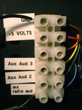
For your application, I would simply run the wires into the box, and have them terminate into a terminal strip like this. Use a few cable clamps to provide strain relief on the outside of the box. Apply some neutral cure (no acetic acid) RTV around the opening (where the wires enter) after you’re finished.