I’ve googled a bit but haven’t found a proper schematic symbol for four-terminal resistors. What I am finding are schematic representations of connecting two wires at each end of the resistor, but that’s not the same thing, and the difference is significant (which is why four-terminal resistors exist in the first place).
Resistance is a property of the resistors we buy, but also their leads and the circuit board traces or wires that we use to connect to them. A four-wire resistor isolates its intended lump resistance from those other forms of resistance, by providing two connection points all the way in to the “active” part of the resistor. More accurately, the distinction is: the resistor maker’s specifications, claims and promises regarding the resistance value and how it depends on temperature, are all officially referencing that internal part of the resistor that is between the pairs of connection points inside. If my schematic is consistent with our creating our own version of a four-terminal resistor by connecting things that way, then the part of the creation that we generated becomes included in the “active” part of the resistor, and no resistor manufacturer can make promises about its behavior. In applications where the resistance outside of the resistor component itself would make a difference, the four-terminal construction eliminates that difference. It’s also sometimes called a “four wire resistor” or “Kelvin wiring”.
I guess I could draw an ordinary resistor with two connections at each end, and then draw a dotted rectangle around this assembly to indicate that those connections are buried inside the component body. But isn’t there an official way to communicate this?
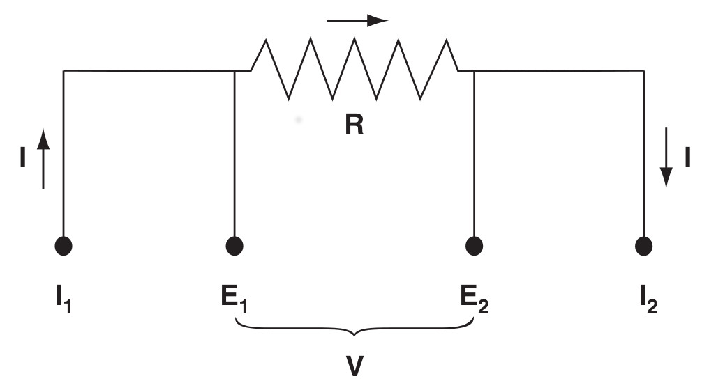
I have only ever seen it drawn the way you describe…resistor with four connection points, usually drawn as diagonals from the end of the resistor. I looked at some schematics resources, but don’t see anything similar. (I often use Wheatstone bridges, so I understand the concept at least a little. It also pops up when using shunts to measure current.)
Assuming a single SMID four-terminal resistor used in application like current sense is there to improve the consistency and to reduce the length of the second pair. I agree with the above that the existing convention is fine for the schematic and mapping the R## to a part or drawing a box will be fine. Or I personally wouldn’t have a problem with that.
I don’t know if there is an “official” schematic symbol for a four wire resistor. But I have seen what you described, so I just went ahead and drew it. I put the schematic symbol in this folder (pptx, pdf, jpg).
I have about 40 stand-alone four-wire resistors in our lab. These are standard resistors, and we use them to calibrate other resistors using a bridge. Most of them were manufactured by Leeds & Northrup, and look like this. They are maintained in an oil bath set to precisely 25 °C. We also have some “air” resistors manufactured by Fluke. They don’t need to be kept in an oil bath.
Now if you’re looking for four wire resistors that are designed to be mounted to a PCB, well, they’re hard to find nowadays. In the 1990s there was a company called Julie Research out of New York, NY that made fantastic four wire resistors that were designed to be mounted to a PCBs. (They had wire leads, just like regular two wire resistors.) I thought they went out of business a while back, but it looks like Ohm-Labs, Inc. bought them out. Their four wire PCB resistors are made-to-order. But I think that was also true with Julie Research.
Yes, that’s exactly what I meant. I don’t think that could be mistaken for multiple traces on a circuit board running to the two wires of an ordinary resistor.
I’m doing some stuff lately with ratiometric resistance measurement and buying 4 lead resistors for PCB mount from a company on Florida’s west coast whose name escapes me, but they were shut down for a week or so around the time I ordered because they got directly nailed by a hurricane last season. They were made to order according to a standard design but with my specified resistance. They have two parallel leads sticking out of each end. They’re almost as big as AA batteries, but they do have power ratings of I think 2 W.
I used to buy these wonderful resistors from Vishay. A friend of mine worked there in the early '70s and gave me a few as souvenirs, and filled my head with wonder at how they made and trimmed them. When I tried to order a few months back, the purchasing agent and I couldn’t get anybody to return our calls, so I guess maybe that business is gone, but I’m not sure.
And our purchasing officer asked if one was a stock item and was told yes. But when we actually tried to get one as a sample… crickets. I think they prefer to do business with Chinese companies buying millions. As you would.
Yea, sounds a lot like the Julie Research (now Ohm-Labs, Inc.) resistors.
Are you concerned about knowing the absolute values of resistance? Or do you simply need the resistors (or resistance ratios) to be stable?
Keep in mind that (I’m pretty sure) most resistors of this type are wirewound. Which means they work fine at DC, but have some reactance at AC. For extra accuracy, you should measure the temperature and compensate for TCR, or maintain the resistors in a temperature-controlled “oven” on the PCB.
And as I am sure you’re already aware, you should take measures to minimize thermoelectric voltage errors when doing the type of measurement you’re describing.
The issue of four-terminal resistors occurs in four-terminal sensing esp. in the PT100 sensors we use in the engine control system I work in, and I have usually encountered the symbol in the form as in the second figure of this German Wikipedia article. (Note: the German schematic symbol for a resistor is a rectangle not a zigzag line).
Usually the straight terminals indicate the higher-current path, and the angled terminals the lower-current (voltage sensing) path.
Yea, that’s another way of doing it. Perhaps it’s even better than my drawing, since it’s less ambiguous which terminals are the current terminals, and which ones are the voltage sense terminals.
Ah, yes, PRTs. Brings back memories of working in the temperature metrology lab. Loved that job. SPRTs are a thing of beauty.
Schematics are not supposed to be the complete documentation for building a circuit. The BOM and assembly notes are also important. For example, the schematic for a transistor says nothing about the particular package that is being used. If there is some piece of information about a part that is important, you can put a note on the schematic, but generally, the part that is specified is enough to make sure that the right device is used.
So, would you say that second figure would also correctly describe two traces to each end of an ordinary resistor? Or would you say everybody should necessarily read that to be distinct, because the wires converge at an angle? I have to say I have only a cursory ability to read schematics…
There isn’t necessarily a difference to be called out between the voltage sense and the current supply terminals. I mean, yes, each terminal is only doing one job or the other, but for low current applications you don’t actually need to distinguish them. I have several four wire ohmmeters and I don’t think a single one of them tells me which lead is which. Of course if we are talking about a shunt for measuring 1000 A with a millivoltmeter, the different terminals aren’t the least bit interchangeable.
By the way, I’m using these resistors with RTDs, yes! They are very very very neat things!
Well, yes, that’s true. I’d like schematics to leave as little ambiguity as practical, but they’re more to help users understand what they’re doing. The documentation involved in actually getting systems built will be much more perfectly descriptive.
I certainly have to know the absolute values of resistance, but the values are somewhat arbitrary. They have to get tested during calibration, and the measured value has to accompany the system through a computer data reduction step. So a 50 or 100 ohm resistor might get selected, but it’s going to get recorded to 5 figures that get used downstream. We aren’t going to control them in a TXO but we might put RTDs or thermistors near them to compensate in software.
Your point is very well taken.
So, I think of four terminal resistors as fundamentally different from two wire resistors, and was just surprised they don’t look different - or more different - in schematics. There’s such a huge volume of information conveyed in a schematic. And it got me wondering. I think I like the dotted line box approach illustrated by CrafterMan best, as it is schematically different, and to the extent that schematic glyphs themselves actually imply something physical rather than being completely arbitrary symbols, the dotted line box does actually suggest what’s going on physically.
That’s no longer the case. Most of the 4-wire resistors, most of the accurate resistors, and most of the power resistors are thin-film or thick-film on substrate. And also, FWIW, much less susceptible to thermo-electric effect than they used to be, when they were made out of bulk-resistance metal.
It screams 4-wire to me.
I confess that I’ve never liked the ISO symbol for resistors (designed to make it easer for draughtsmen to draw with a pen!) partly because It’s harder to tell if it’s a resistor or something else, and I could be confused between a 4 wire resistor and a 4-wire semiconductor. But it’s definitely a 4-write device when it has wires coming off at an angle from the attachment point – even though that’s not normally the way the look physically.
Really? I’ve only bought wound foil and wound wire in the half-watt to maybe 4 watt range. I’m not sure I’ve ever seen a thin or thick film power resistor in the cylindrical axial lead package. Now, one of those ones with a heat sink tab, those could well be thin film.
You’re confusing the temperature coefficient of resistance (TCR) with thermoelectric offset voltages.
Yes, precision 4-wire resistors and shunts use alloys that have a TCR close to zero at room temperature. But thermoelectric offset voltages are always a problem in circuits that use these resistors. (These are voltages that inevitability show up in a circuit due to temperature differences and dissimilar metals.) There are three ways to minimize errors due to thermoelectric offset voltages:
Make measurement, reverse polarity, then average the results.
Use AC excitation, and ignore the DC component.
Voltage offset compensation. (Turn off excitation, measure voltage, and then subtract this voltage from measured voltage.)
It’s Precision Resistor Co., Inc. of Largo, FL that I’ve bought from most recently. I’m buying 0.1%, as I don’t care much about the value as long as I know very well what it is. Their temperature coefficient was low; I really need them to have a very similar resistance while the power level changes.
I don’t remember hearing of Julie Research. Ohm-Labs sounds familiar, but then that might just be because both those words appear frequently in this realm.