Practical question about LEDs

I want to backlight a little LCD clock I have. It’s sort of a project too, so I know there’s an easier way than this. What I want to do is connect a blue LED to a 3V voltage source. I want the LED to have a very low profile, and the best viewing angle and brightness to illuminate an area about 1 x 2.5 inches. I’ve looked at SMDs, 3mm rounds, rectangulars, etc. I know blue LEDs aren’t the brightest, but I like blue.

Anyone have any insight or advice?

Have you tried using a blue LED with the display to see if the display looks O.K.?

I think blue LEDs have a voltage drop of around 3.4 V. I normally don’t recommend powering a single LED using a constant voltage source, but in this case you can probably get away with simply hooking the blue LED directly to the 3 V source. But I would measure the current through the LED, just to make sure. (The current should be less than 12 mA.)

For maximum brightness, you’ll want to supply voltage such that the LED gets it’s peak specified current, usually about 25mA. Find a source in the clock and use an LM317 adjustable voltage regulator in current limiting configuration. You’ll need to account for about 2 volts for the 317 to drop. If this clock is battery powered, you might have a hard time finding a suitable source for 3volt+ LEDs. It’s not ideal but you could always use resistors to drop the supply voltage, too.

I’d look into rectangular side emitters if you can find them. These should concentrate the light in a predicatable and desireable direction.

We use some surface mount blue LEDs in an industrical controller that I work on. They are plenty bright. You can always put a row of them along one or more edges ofthe display, angled up towards the display. You can also stick a big honkin LED behind the display and have a reflective surface around the outside of the display angled at a 45 deg angle so that it reflects all of the light from the LED(s) towards the display, but takes up very little real estate around the display.

Off the top of my head I would have probably thought so too, but that LED thread we had last week made me look at the voltage/current curve of a blue LED off of the data sheet. The one I looked at was pretty happy with a forward voltage of 3.4 volts. It looked like it went poof at 3.6 volts, and it also looked like it was near completely dark at about 3.1 or 3.2 volts. Not much of a range to work with.

jnglmassiv is recommending the standard LM317 circuit that you usually recommend. I’d go with that, or just a dropping resistor. Either way, the OP is going to need more than 3 volts to drive the circuit. There are 3 to 5 volt converters out there if there’s no higher voltage available in the device. Maxim used to make one that was cheap, but I’m not sure if it’s still available or not.

Thanks, guys; I can provide a higher voltage source and add a resistor, if 3.0V doesn’t cut it. As for the LED & viewing angle, what do you think of the edgelight LED sets? Is this what you meant by a rectangular side-emitter, jnglmassiv?

Oh, and one more thing occurred to me – is water-clear the way to go, or will I get better backlighting from a diffusive lens?

The max operating current for most red LEDs is around 20 mA. For a blue LED, the designer had better look at the datasheet. The blue LEDs I used on a previous project had a maximum forward current of 12 mA. But I just did a google search on blue LEDs, and found some with a maximum forward current of 20 mA. Again, the designer must read the datasheet.

The LM317 needs about a 3 V drop across it when configured as a current regulator. So in order to use a LM317, the source voltage should be at least 7 V. So obviously a 3 V source won’t work.

This statement puzzles me, because in my experience, blue LEDs are nearly always dazzlingly bright - often too bright for the application. They are often not particularly good as backlights, that’s true.

Sound good, but you also want to be thinking about efficiency, too.

Most linear LED circuits have three components: the power source, a series current limiting device (CLD), and the load (i.e. LEDs). The CLD is usually a resistor or a LM317 configured as a current regulator. The efficiency of the circuit is primarily determined by the power dissipated by the CLD. The less power that is dissipated by the CLD, the more efficient the entire circuit is.

The power dissipated by the CLD is I[sub]CLD[/sub]*V[sub]CLD[/sub], where I[sub]CLD[/sub] is the current through the CLD (which is equal to the current through the LED), and V[sub]CLD[/sub] is the voltage across the CLD. To minimize the power dissipated by the CLD, you need to make I[sub]CLD[/sub] small, V[sub]CLD[/sub] small, or I[sub]CLD[/sub] and V[sub]CLD[/sub] small.

Well, you can’t do much about I[sub]CLD[/sub]. After all, that’s the current through the LED, and it is specified right up front. But you do have control over V[sub]CLD[/sub]. The lower you can make V[sub]CLD[/sub], the better.

The easiest way to make V[sub]CLD[/sub] small is to make the voltage of the power source (V[sub]PS[/sub]) just slightly higher than the nominal voltage across the LED (V[sub]LED[/sub]). And then use a resistor as your CLD. (If the voltage across the CLD is less than 3 V, you can’t use an LM317 as a CLD. If it is higher than 3 V, you can use a LM317 as the CLD, and it is the preferred method.)

Let’s look at some examples:

Let’s say your LED has a maximum operating current of 20 mA, and a nominal voltage drop of around 3.4 V when operated at max current. To make the circuit efficient, you make the voltage of the power source V[sub]PS[/sub] = 4 V. This means you’ll use a 30 Ω resistor as a CLD. Using these values, 85% of the power will go to the LED, and 15% will go to the CLD. Not bad.

But instead of using a power source of 4 V, let’s say you use a power source of 6 V (V[sub]PS[/sub] = 6 V). This means you’ll use a 130 Ω resistor as a CLD. Using these values, 57% of the power will go to the LED, and 43% will go to the CLD. This is not nearly as efficient as using a 4 V power source.

It obviously gets a lot worse when you make the power source voltage even higher. Say you use a power source of 9 V (V[sub]PS[/sub] = 9 V). This means you’ll use a 280 Ω resistor as a CLD. Using these values, only 38% of the power will go to the LED, and 62% will go to the CLD. This is sucks. (Also note that you can use a LM317 instead of a resistor. While the current regulation will be a lot better, the efficiency will not be any better.)

Now having said all of that, minimizing the voltage drop across the CLD may not be the most important thing on earth:

  1. While minimizing the voltage drop across the resistor improves efficiency, it decreases its ability to properly regulate current if V[sub]PS[/sub] is not well regulated.

  2. For most applications, maximum efficiency is only important for battery operated devices. And besides, if efficiency were very critical, the designer would opt for a PWM circuit to drive the LED.

If this is the case, my original idea of simply hooking it up to the 3 V source obviously won’t work. :wink:

Luminosity function maybe the reason for the statement.

Possibly, although there is the simple fact that blue LEDs are generally just higher-power devices than the standard red or green ones to which we are so accustomed.

The 3 and 5mm blue/white1/white2 ones I’ve used are usually 30mA max but I usually shoot for 25. It looks like many of the performance specs are taken at 20mA forward, though.

Thanks again. What I have is a variable-voltage car-lighter adapter that I plan to wire into the circuit; it’ll convert the 12V supply into 3.0V, 4.5V, 6.0V, etc. I’ve been holding off on buying the LEDs because I want the ideal trade-off between size, viewing angle, and brightness. I’ve been judging brightness by the lumen ratings in the data sheets, and the blue ones always have the lowest numbers – but it’s true that they always LOOK damn bright.

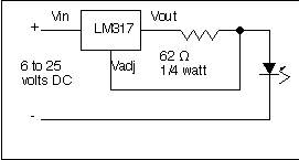
Is this voltage source going to be too variable to do the job without a regulator? The LM317 looks pretty complicated to set up. Any other comments spring to mind?

It ain’t complicated.

62 ohms is for 20 mA. For other values, use I=1.25/R.

Run the circuit off of the 12 volt input. You need 6 volts or better, which means it won’t work on your 3.0 and 4.5 settings.