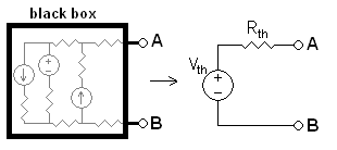
The first-order model for the cell is an ideal voltage source in series with an ideal resistor. The former is called the cell’s Thévenin equivalent voltage, a.k.a. the cell’s open circuit voltage. We’ll call its voltage V[sub]th[/sub]. The latter is called the cell’s Thévenin equivalent resistance, a.k.a. the cell’s internal resistance. We’ll call its resistance R[sub]th[/sub]. Just like the schematic here. Both of these quantities are unknown for the cell. Measurements will make them known.
You will take two voltage measurements (V[sub]1[/sub] and V[sub]2[/sub]) with two different load resistors (R[sub]1[/sub] and R[sub]2[/sub]). In other words, connect R[sub]1[/sub] to the cell and measure the voltage (V[sub]1[/sub]), then connect R[sub]2[/sub] to the cell and measure the voltage (V[sub]2[/sub]).
During the first measurement, V[sub]th[/sub] must be equal to the voltage across R[sub]th[/sub] + the voltage across R[sub]1[/sub] according to Kirchhoff’s voltage law. The voltage across R[sub]1[/sub] is simply what you measure with the voltmeter (V[sub]1[/sub]). The voltage across R[sub]th[/sub] is determined using Ohm’s Law; the voltage across it is (I[sub]1[/sub])( R[sub]th[/sub]), where I[sub]1[/sub] is the current in the circuit. The current in the circuit can be calculated by applying Ohm’s Law to R[sub]1[/sub], i.e. I[sub]1[/sub] = V[sub]1[/sub]/ R[sub]1[/sub]. Therefore, the voltage across R[sub]th[/sub] is (I[sub]1[/sub])( R[sub]th[/sub]) = (V[sub]1[/sub]/ R[sub]1[/sub])( R[sub]th[/sub]) = V[sub]1[/sub] R[sub]th[/sub]/R[sub]1[/sub]. Thus
V[sub]th[/sub] = (V[sub]1[/sub] R[sub]th[/sub]/R[sub]1[/sub]) + V[sub]1[/sub]
Doing the same for the second measurement we get
V[sub]th[/sub] = (V[sub]2[/sub] R[sub]th[/sub]/R[sub]2[/sub]) + V[sub]2[/sub]
Now we have two equations with two unknowns (V[sub]th[/sub] and R[sub]th[/sub]).
Combining the two and solving for R[sub]th[/sub]:
R[sub]th[/sub] = (R[sub]1[/sub] R[sub]2[/sub]( V[sub]2[/sub] - V[sub]1[/sub])) / (V[sub]1[/sub] R[sub]2[/sub] - V[sub]2[/sub] R[sub]1[/sub])
Now that R[sub]th[/sub] is known, you can easily solve for V[sub]th[/sub]:
V[sub]th[/sub] = (V[sub]1[/sub] R[sub]th[/sub]/R[sub]1[/sub]) + V[sub]1[/sub]
Keep in mind, however, that V[sub]th[/sub] and R[sub]th[/sub] are dependent on everything. This includes the load resistance (current), temperature, amount of charge in the cell, phase of moon, etc. If you were to make these measurements with a set of resistors that were twice the values of R[sub]1[/sub] and R[sub]2[/sub], for example, you would get a somewhat different answer for V[sub]th[/sub] and R[sub]th[/sub]. Also note that time can be an issue; the voltage across the resistor will vary with time. Ideally, therefore, you want both measurements to occure within one or two seconds of each other. A smart way to do this is to use two resistors in parallel for R[sub]2[/sub]. Here’s an example: grab ya two, 100 kΩ resistors. During the first measurement, R[sub]1[/sub] will be one of the 100 kΩ resistors. During the second measurement, R[sub]2[/sub] will be both 100 kΩ resistors in parallel (R[sub]2[/sub] = 50 kΩ). The second resistor can be quickly connected across the first resistor using alligator clips, and thus the second measurement can be taken very quickly after the first measurement.
And for bonus points, include the input resistance of the voltmeter.