Home wiring - layout of breakers in a panel?

This is in California, in the US, if it makes any difference. I’m interested in both what the NEC says and what the laws of physics say; the former is locale specific, the latter not.

We recently had an electrician give us a quote on a sub-panel ($3200…eek! and that’s after we offered to do the trenching and non-electrical prep). He observed in passing that he would like to re-arrange our existing main breaker panel so the “larger” circuits, meaning higher voltage, are at the top, working down to the lower ones at the bottom. He said otherwise there could be problems with “lights dimming”, which we’ve never experienced in the 5 years we’ve had the main panel. I wired the main panel myself and I did it to above our local Code - the city inspector loved it.

This got my BS detector going. Why would the order of components in a circuit affect the current available to each? My understanding is that a circuit is taken “holistically”, and that one shouldn’t view it that the current flows to each component in turn, and those “downstream” get less if there are some heavy eaters upstream. On reflection this is even sillier in the face of AC, which changes “direction” 60 times per second. Surely the potential drop across a given component is calculated as I x R, independent of what is before or after that component in the circuit? Or is there a concept of order of components?

I then got to thinking about Ohm’s law - V=IR, where there is no “time” variable and no variable to account for the order of components. It’s simple - just voltage, current and resistance. I believe in the case of AC, if I remember school physics classes from aeons ago, that V is the RMS voltage, but I don’t think that changes the conclusion - or does it? Perhaps because RMS is an “over time” averaging, it causes the order of components to start mattering?

I googled this quite a bit and the only relevant hit I found was this, which says:

Unfortunately it doesn’t say why. Is this just one of those conventions electricians use, for consistency and to have one less thing to think about? For example, some electricians like to have a convention that says incoming power should come in at the top left of a receptacle and the downstream feed goes out the bottom right. No electrical reason for this, but it does help us as humans.

I know that a best practice is to try to balance loads on each arm/phase of the feed, so that they cancel out in neutral allowing you to load the panel more efficiently, but I don’t think that’s what he was talking about.
The idea is that the high-draw loads will be closest to where the incoming power enters the panel and have the shortest possible amount of “wire” between them. It’s really just window-dressing as the bus in a modern panel can handle a load of a few hundred amps, so it really doesn’t matter where breakers are located. As long as he’s not charging you anything extra for re-arranging breakers, it won’t be particularly helpful or harmful.

I have seen older panels where there were physical constraints on where two-pole breakers could go because they were too big to fit elsewhere, but modern breakers are able to go wherever you want them.

Can you imagine any way in which a particular arrangement of the breakers could lead to load problems on circuits, manifested as dimming lights? Also, why would you care about minimizing the amount of “wire” between the incoming power and the loads? Isn’t the current flowing in a circuit independent of the order of the components?

More wire does lead to more resistance though, which causes a voltage drop when current flows. Although the voltage drop is miniscule in a breaker panel, given the thickness and length of the bus bars.

FWIW, the electrician surely meant higher amperage, not voltage when he said they should be at the top; all circuits essentially run at the same voltage, 120 volts 2 phase (or 240 volts split-phase which is the same thing); for 240 volts, you just use two 120 volt lines of opposite phase (a dual breaker is used, each half carrying 120 volts).

This was filtered through my wife, so it’s possible he did say amperage. However the quote from the NEC mentions voltage, so I assumed he had said that. Perhaps the NEC really does mean put the 240V items at the top and the 120V items lower down?

High voltage devices are generally considered to be high current devices as well. After all, if they didn’t need that much power they would just run off of 120 instead of requiring 240. Therefore it does make sense to put the high voltage breakers at the top of the panel.

If you understand V=IR then you understand enough to know why you want the higher current stuff at the top of the box. Every piece of copper is a resistor, so each section of copper in the box between one breaker and the next is a resistor. The more current you have flowing through that strip of copper, the higher the voltage drop across that piece of copper (V=IR, more I equals more V if R stays constant). You’ll get less of a voltage drop down through the box due to resistive losses if the higher current stuff goes through the shortest sections of copper.

That said, in the real world, with a modern breaker box, it doesn’t make that much of a difference. The metal inside a modern box is thick enough that the voltage drop is going to be fairly small even if you have all of the higher current loads switched on.

If the electrician isn’t going to charge much for it then go for it. Otherwise your existing setup probably isn’t going to cause you any problems.

I have been reading my 2011 NEC, for the better part of an hour to check on this. I can find nothing that states what was said in the OP. Electricians myth I suspect FWIW

CAPT

Thanks for the real tech info ECG

With most electrical meters you will get the same voltage reading at the top of the buss bars that you eill get at the bottom. Fully loaded I would guess it would be on the order of 0.01 volts, that would not cause dimming of lights.

I thought that running on multiple phases brought inherent efficiency gains. In computer power supplies, I remember reading a few times that the same unit run on 240 was noticeably more efficient.

For a specific model that might be true, but generally there’s nothing inherent in the supply voltage that will make a computer type power supply more or less efficient.

For a given amount of power, you can increase the voltage and decrease the voltage by the same factor. In other words, if you double the voltage the current will be reduced by half, and if you quadruple the voltage the current will be one-fourth, etc. The resistive losses (energy that gets wasted turned into heat) through conductors is proportional to the square of the current (current squared times the resistance), so if you are transmitting the electricity over a distance, these resistive losses get to be rather significant. This is why the power company boosts the voltage up to very high levels, tens to hundreds of thousands of volts for transmission lines, and several thousand volts for distribution lines. Over the short distances involved in a single rack of electrical equipment or inside a computer power supply though, the resistive losses are pretty much negligible.

A modern switching power supply, like what you find in a computer these days, is going to be about 90 to 95 percent efficient, regardless of the supply voltage. Many of them will even function efficiently over a fairly wide range of voltages, typically anywhere from 100 to 240 volts, which allows the same power supply design to be used in multiple countries without even requiring a switch to select the line voltage in use.

Some old larger computers used to run off of 3 phase power (old Vax computers from the 1980s come to mind). You could run them off of a single phase, but they wouldn’t run very efficiently. This was due to the design of the power supply though, and not due to the difference between single phase and 3 phase power, or any voltage difference involved.

Don’t desktop computers still use transformers in their power supplies, though?

Power supply designs vary, but most of the big bulky transformers went out when the 120/240 volt switch on the back of power supplies started to disappear as well. That switch used to either switch the windings on the transformer, or it would switch a voltage doubler in or out of the circuit just after the transformer.

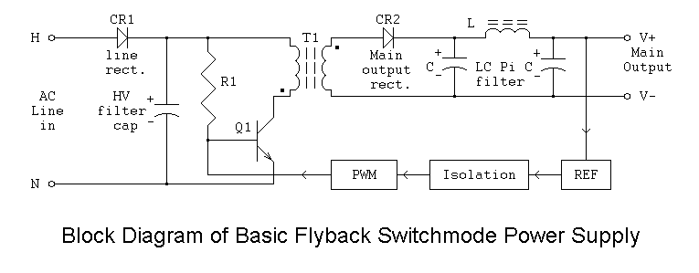
In their quest to make power supplies that are both smaller and more powerful, most power supply manufacturers have gone instead to converting directly to DC, then switching that on and off through a transformer at a much higher frequency, then rectifying and filtering that transformer’s output. It’s basically combining the 120/240 to lower voltage conversion into the switching regulator, which used to be separate stages in older power supplies. You end up with a lower parts count and significantly smaller transformers, which translates into lower cost, smaller size, greater power, and a power supply that will work over a wide range of main AC voltages and frequencies without the need of a voltage selector switch.

This is an oversimplified circuit, but it’s the basic idea of how they typically do it these days.

A real power supply will have more than one output voltage (3.3, 5, +12, -12) and will have more filtering and some protection circuitry on the AC input side as well.

Sounds like BS to me.

The resistance of a thick copper wire or bus bar measured in inches is negligible. If a device draws down the current enough to make the lights blink (remember the old refrigerators doing that when the compressor started?) then the current drain causing voltage drop would be manifest through the entire panel no matter where the large load was placed.

But then, I never did finish fourth-year physics so I only have a minor in it.

(10 feet of 12 gauge wire would have about 0.016ohms, according to my friend Google. I’m guessing a foot or so of thick metal’s resistance can be ignored.)

It’s like saying if we put the drain near the deep end of the pool, you won’t notice the pressure drop near the shallow end when you pull the plug. Basically, it does not matter anywhere at all.

the speed of electricity / voltage / current timewise is negligible too - on the order of microseconds. THIS - Velocity factor - Wikipedia - says it’s on the order of 70% to 80% of the speed of light. Nanoseconds.

Actually, no; even ancient IBM PC power supplies were based on SMPS technology (see picture here of the power supply for the IBM 5150 aka first PC, which clearly shows a SMPS); the voltage switch is used with a voltage doubler circuit so that on 120 volts it double the voltage (around 300 volts DC to the switching converter) and on 240 volts it acts like a normal rectifier (also providing 300 volts). I believe that the only computers made with regular old linear transformer-based power supplies predated the PC. I have never heard of the switching *after *the transformer either; it is much more efficient to use the transformer’s primary to do the job than make a voltage doubler (would need large capacitors for one, possibly cheaper as well).

The real reason for a lack of a voltage switch is that newer power supplies (although you can still find them with a switch) use power factor correction, which not only corrects the power factor but provides a constant voltage to the switching converter (it is also possible to make a SMPS that handles a wide input voltage range by itself (usually using a flyback topology), but the topology used in higher-power supplies, a forward or bridge-type converter, doesn’t work well on a wide range).

Don’t opposite sides of the panel (or maybe adjacent circuits) share a neutral wire? If that’s the case, then you want two devices with high current on opposing phases so the neutral wire doesn’t melt. So the electrician is perhaps intending to pair them up from highest to lowest. The location in the box isn’t really relevant, but top-to-bottom is as good a layout as any.

No, phases alternative from space to space top to bottem, if they alternated side to side you’d have to design a breaker for 240 volts that was as wide as the panel. All the neutrals and grounds are screwed together on a common bar.

I put the bigger breakers on top in my house, not because they worked any better, but it looked better, and was slightly easier technically. Some of the double wide breakers had big thick wires so I could tie up all the smaller ones out of the way while dealing with the thick wires, keeping them towards the back so the more numerous thin wires could go in front. Also, a 240 volt breaker always takes two spaces, if you start running out of room the 120 volt breakers working your way down you can use tandems if you make sure that you make very very sure you’re not putting both phases of a shared neutral onto a tamdem.

But short answer, the only consideration in a modern panel is making sure shared neutral circuits go to different phases. Anything else that “has to be” is BS.

The net current flow through the neutral wire would be zero if the hot wires are 180 degrees out of phase and the same load is placed on both, referred to neutral (although this probably isn’t done often when 240 volts are needed, instead going from one hot wire to the other); thus the neutral doesn’t need to be any thicker than the hot wires.

[QUOTE=Michael63129]
The net current flow through the neutral wire would be zero if the hot wires are 180 degrees out of phase and the same load is placed on both, referred to neutral (although this probably isn’t done often when 240 volts are needed, instead going from one hot wire to the other); thus the neutral doesn’t need to be any thicker than the hot wires.
[/QUOTE]

For the sake of completeness, as there was some mention of 3-phase power above, it is sometimes necessary to upsize the neutral. Non-linear loads like older electronic ballast fluorescent fixtures and computer power supplies can kick up the neutral current to a theoretical maximum of 1.7 times the “hot” current, which led to a class of power equipment called “K factor-rated” with double-sized neutral wiring. Modern lights and computers have power-factor compensation built in to minimize this, but when these things first became popular in offices, they were causing widespread problems for building engineers until the nature of the out-of-phase currents was understood.

Amen to that.
When I worked for a department store chain at one store I spent a day trying to figure out what was going on. On one set of breakers (3 seperate breakers AB&C) the neutral was runnning over 25 amps while the highest leg of the three waas around 17 amps. And the panel neutral was also high. The department being feed by this panel was TV and electronics.
This went aginst everything I was taught. Really had me up against a wall. That is until a few days later I learned about the electronic thing. Had to run a seperate neutral for one of the circuits.

Yeah, we had a salesman trying to sell our building manager for a fairly large building on dimmable flourescent lights. Basically they clipped the sides of the sine wave to make it a square wave - same voltage, less time and thus less amperage. The head of electrical engineering took one look at it and said “No &*^$ way!”. That technique would send the currents wildly out of phase and risk overloading and starting a fire in the common neutral wire. All 3 phases fed one common neutral.