No, I’m not going to Newegg and picking out a motherboard and a case.
I’m building a computer from first principles. I’ve long been fascinated by the early history of digital computing, before transistors and even before vacuum tubes. Back in the late 1930s people built several successful computer models using relays. The main pioneers in the area were Konrad Zuse (who built several relay machines) and Claude Shannon, who wrote the main theoretical treatise on them.
(Claude Shannon, in case you didn’t know, basically invented the 20th century, along with everyone else at Bell Labs.)
So I’m making a fully programmable digital computer out of relays and will document it in a series of awesome YouTubes.
Here is the first video in which I explain the basics of logic gates, and how to make some with relays, and demonstrate a simple prototype.
My goal is the make the videos easy to understand for anyone, whether or not you know anything about digital circuitry, but hopefully still entertaining for hardcore computer nerds.
The next video (which I hope to finish before the weekend) will focus on building the first major component of my computer - the 16-bit adder.
My high school had a project of unknown provenance that consisted of a rack seven feet high, with hundreds of discrete logic cards in the back, and a vast array of switches and lamps in the front, connected with a large, square plugboard. The cards were about the size of an index card and each contained something like an AND gate or flip-flop, built from discrete components. The plugboard swung in and out on a surprisingly massive mechanism a bit like a laundry presser - swing it forward, use a chart to connect logic elements with 1/4 inch plug jumper wires, swing it back to see if the logic design worked. Built all kinds of basic logic devices over my sophomore year, learning it all from first principles (of “well, that didn’t work”).
Came back my junior year and it had all been scrapped. Yes, we had a new HP desktop computer (a 4-bit, BASIC-programmed one). Yes, the first generation of IC-based logic teachers (using the gosh-wow 4000 series CMOS chips, even) was available. But I honestly cried to find my monstrous old Frankenstein system gone…
I would be curious why you’re approaching this with relays instead of moving a couple of steps up the technology ladder and building your machine out of discrete logic gates. I suppose one’s approach to this would depend on what one regards as “first principles” and the kind of challenge (and cost!) you want to set yourself. But I would certainly find it enormously challenging and satisfying to build even the most incredibly primitive computational device out of logic gates, and AFAIK the things are dirt cheap, especially in quantity.
I actually owned a simple small version of something like that, which prompted my comment above. It was basically a case, about the size of a briefcase, with a plugboard in front marked up with logic gate symbols and the actual gates correspondingly wired to it inside the case, along with switches and lights that you could connect into the circuits. IIRC there were some momentary-contact switches and a whole row of rocker switches that could be used to enter binary data. That was it. It was a completely general-purpose collection of logic gates, switch inputs, and lights for output. There was a whole spaghetti pile of patch cords of varying lengths and colors and you could build whatever you wanted. It was lots of fun and was a good toy for learning how to build simple computational functions out of real logic gates.
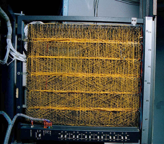
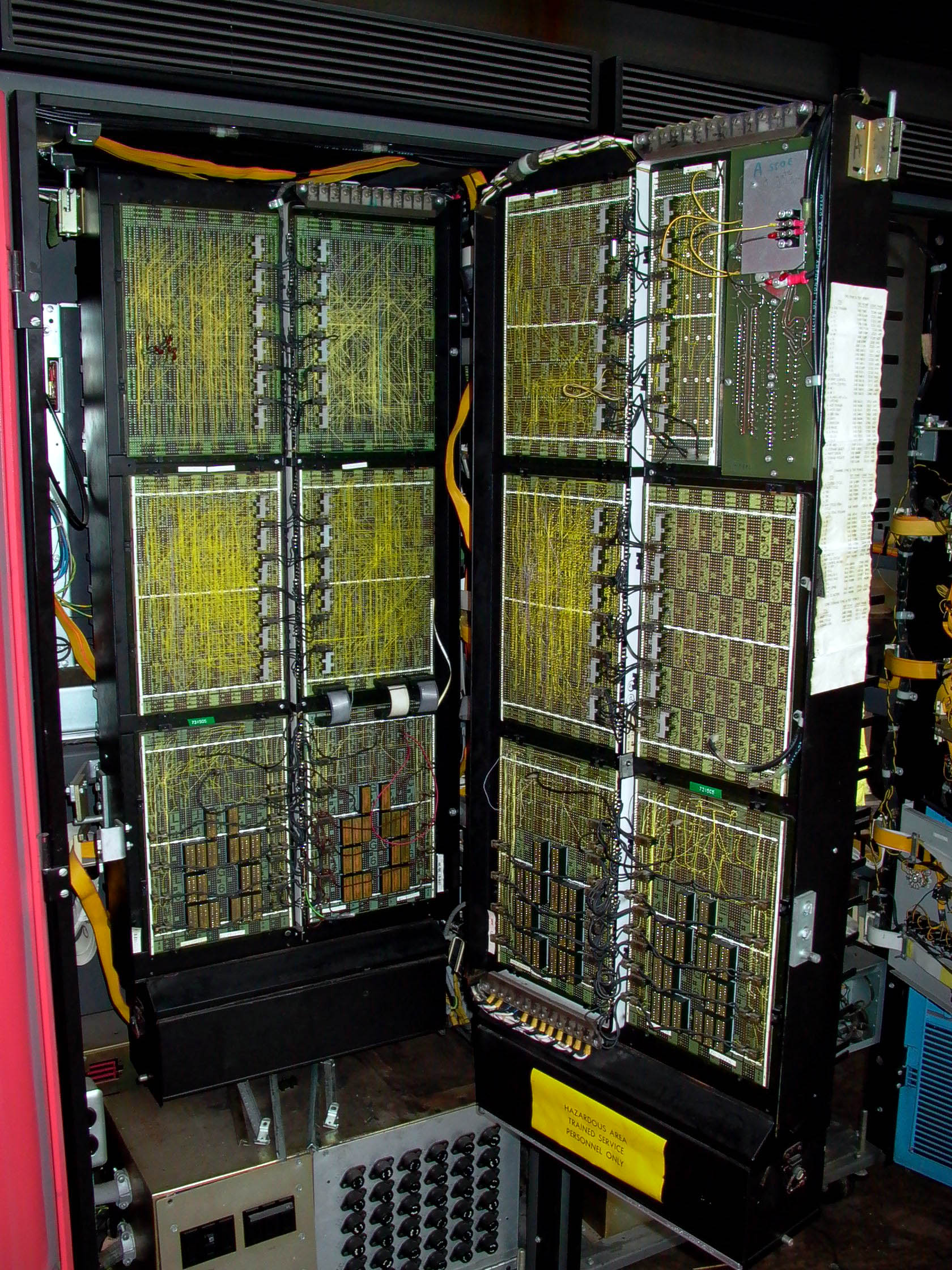
Back in those days real computers were built with discrete-component cards that were usually little more than multiple collections of gates on a card, and they plugged into standard backplanes in long colored rows. The vastly complex interconnections between them were done on the other side of the backplane by wirewrapping between about a gazillion pins – this is what a small backplane might look like on the wiring side, and this is a bunch of them in a cabinet. Today that whole freaking thing would be a chip about the size of a postage stamp.
When I was a kit, I got a computer kit. It was totally mechanical and consisted of plastic panels that slid back and forth in a frame. There were wire bales (like loops) and these would engage with other sliding panels to create your logic gates. You programmed it by placing little plastic tubes on the backs of the sliding plates to engage the wire bales. Figuring out where to put the tubes took a lot of effort, since you would basically be translating a logic diagram to a physical device, but it could solve all sorts of mathematical and logic problems.
I may try to find a picture of it to link in a later post. This was in the 60s and I don’t ever recall seeing them advertised. My parents just found it for me one Christmas.
There’s an exchange about this in one of the Dope books that devolves down to sticks, rocks and grains of sand. We don’t - do not - need to repeat the devolution.
I will say I always wanted one of those “computers” so breathlessly advertising in the back pages of Popular Mechanics et al.
I started working out the basics of a computer basic logic chips long, long ago. I was already building computers out of early CPU chips like the 8080 and 6800 and that occupied all of my time and I never got back to the basics. I understand why this is appealing though. Haven’t had a chance to look at your video yet but my first step was to create the incremental program counter and I was working out how to recognize a JUMP instruction to replace the current counter a new address. Lot of work involved just in those basics. Good luck with this.
Also, you can see them operating, which better elucidates what the machine is actually doing.
And they go clickety-clack and it’s great.
They still make stuff like that - I know there’s a companion version that I got at RadioShack as a kid with mostly analog stuff on it. I think Elenco may still make them.
Yeah, wire-wrap is gnarly. I’ve never done it, but it looks kinda fun.
I like having nice neat PCBs, though. And they’re pretty cheap to get made nowadays.
I finished the first (real) phase of my project which is building the binary adder and it works great.
I’ve documented the build with another video here. This video goes into the basic theory of adders and then shows the four-bit adder board I made. I chain four of those boards together to make a 16-bit adder. 64 relays!
Next up I’ll either do the logic functions or the processor registers; I haven’t decided yet. But first I have to finish the adder by making an interface for it so it can sit on the main bus without wires going all over the place.
I subscribed. I look forward to watching this project as it progresses.
I read a lot of golden age science fiction - in the past, the future was going to be full of robots and computers made from relays and coils. I love it.
One thing that you didn’t mention about the “shORt gate” is that it’s very important that you don’t tie the input signal to ground in its off state. Otherwise, you really will have a short and fry your board.
I see from your schematic that it’s wired correctly, though you may want to put in an annotation or something to warn people about this. Do it with an Arduino and you’ll probably damage it.
Have you thought about more efficient gate configurations? For instance, you can get an XOR/XNOR out of a single DPDT relay by tying both A and B to the two coil inputs. If they’re at the same voltage (either high or low), the coil won’t energize; if they’re opposite, it will. I haven’t worked out yet whether you can get a full adder out of fewer than 4 relays, but it seems like it might be possible.
Ah, that was you! I’m now up to a whopping 18 subs.
Thanks! I don’t have anything else on YouTube, really. I’m constantly amazed at what I can achieve with a couple hours in Keynote and iMovie.
When I was in high school, I made movies using our 3/4-inch Sony U-Matic deck-to-deck editing console. You got one effect: cut from A to B. And each edit took forever. And there was no YouTune to upload your amazing art to.
Definitely. One upcoming project is an interface board to tie the four adder modules together; that board will have pulldowns for all the signals to ensure that everything has a nice proper ground state. Right now everything is just flapping in the breeze, as it were. OK for relays, but a pain when you want to interface with ICs like my Arduino programs which I use to test stuff.
Good point.
That’s an interesting idea, I haven’t thought about it. So far, all my designs assume one input = one relay.
I will definitely need XOR and XNOR for the logic functions of my ALU. I’m currently working out how to squeeze the most possible functions in the fewest relays. I’m sure Konrad came up with some very clever ways to do them, I’ll have to check my notes.
Some more thinking on the subject–a SPDT relay gives you the equation (X ^ Y) ? Z : W. And DPDT, while it has to share the (X ^ Y) part, can have two different Z and W pairs. You can use this to pack any two of several gate types into a single relay.
OR: (A ^ B) ? 1 : A
AND: (A ^ B) ? 0 : A
XOR: (A ^ B) ? 1 : 0
XNOR: (A ^ B) ? 0 : 1
IMPLIES: (A ^ B) ? B : 1
I don’t think there’s any way to get NOR or NAND, but already a combined AND+XOR gives you a half-adder with just one relay (note that this requires that your logic is never left floating, so no “short gate” tricks).
It’s a really great start, and has the potential to grow quite fast, and gain a loyal subscriber following, I think. I could see schools and colleges using this as a teaching resource.
Are you set up to monetize your YouTube videos? If not, you should.
