If you’re having that problem with wire nuts, then you’re either doing something very wrong, or getting defective wire nuts.
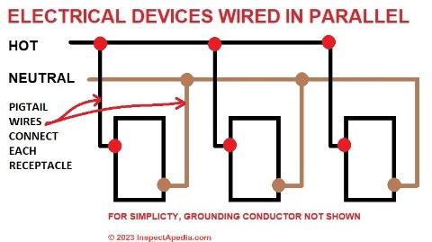
In any event, the NEC requires that grounds and neutrals be wired in such a way that a failure of a connection to a device will not propagate to other devices further down the chain. That pretty much means pigtailing them in the manner that we are discussing.
I developed a strong dislike for those spring clip connectors when I worked for a major department store. We had too many failures when they were used in remodels. If I was changing a ballast and spring clips had been used I would cut them out and use wire nuts. I would guess the failure rate was along the lines of about 10% of the time. This was not just in one store but many store with many different contractors. The failure rate was so high that before the remodel could be completed they would begin to fail.
Now I will admit that over time I began to think the failures were when they were used with THHN stranded wire. I do not remember seeing many failures when they were use with solid TW wire.
No. They are wired in parallel. If you wired them in series nothing would work correctly.
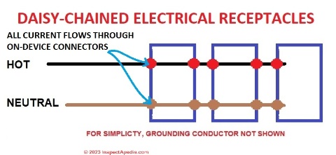
Topologically, most are daisy-chained (as opposed to separate home-runs back to the power source) but they are always electrically in a parallel circuit.
One of the problems with pig-tailing, as opposed to daisy-chaining, is that you make it more difficult to get everything back in the box. You already apparently have this problem. Per NEC Art. 314, each 14 AWG conductor (hot and neutral) passing through or entering a box requires 2 cubic inches of box volume. A duplex receptacle connected to the 14 AWG conductors requires 4 cubic inches. This volume allowance is for the physical space that the conductors (including the 6 inches required to be available for making connections) and connectors (wire nuts), and for the heat the current-carrying conductors generate. The 14 AWG grounding conductors only require a total of 2 cubic inches, no matter the number, as long as they are all connected to the same grounding point.
Many single-gang boxes do not exceed 13 cubic inches in volume, and many cheaper boxes have as little as 7 or 10 cubic inches. If a hot, neutral and ground enter a box, are stabbed to a duplex receptacle, and then continue on to the next receptacle box through three stabbed conductors, at least 14 cubic inches are required in the box. A 4" x 2-1/8" x 2-1/8" metal box is the SMALLEST box you can use for this installation and still comply with NEC. Adding additional conductors or pigtails, or using a smaller box, is a no-no.
OTOH, if they are plastic (nonmetallic) boxes, they will have a volume printed on them. That volume may be less or more than an equivalent metal box.
I thought I’d try these out and bought a big bag and a small bag last time I was at the hardware store, but on my first project I was connecting a device that had stranded wire. Although the connectors say they’re designed for use with stranded, I couldn’t get it to go in solidly. (No, the stranded wire wasn’t too thin.) IME they’re fine for solid, but since I deal with both kinds, I decided to return the big bag I hadn’t opened yet.
Wago connectors are similar, but use a lever to clamp the wire, and seem to be a better design, but they’re also up to ten times more expensive than simple wire nuts. Here’s a video that compares all three.
Sometime in the near future I may be replacing a lot of the old ungrounded two-wire receptacles in our house with three-prong, and when I do, I may invest in some Wago connectors.
On stranded wire I have seen too many failures with the push on connectors and stranded wire and would not use them. Now that levered push on is interesting.
I meant in and out from one outlet to the next, i.e. daisy chained. A “parallel” connection in this context would be something like a junction box with three sets or wires out going to three different outlets.
Obviously it wouldn’t work if the wires themselves weren’t in parallel.
I have to accept the electrical people know what they are doing, but it seems to me if you have a failure in a receptacle then any failure is a problem - it should not be constructed such that you don’t notice there’s a problem.
If your neutral is disconnected then I don’t see the circuit working for that outlet or any down-chain. Using pigtails so the problem is not apparent just seems a bad idea. You want to notice wiring issues, the sooner the better.
My house built in 1962 had a copper (uninsulated) ground included with the black and white wires in the feed; with the old 2-prong outlets it was tied to the box. So for grounded appliances, you could attach that spade ground wire thingy to the outlet center screw that held the cover plate - those were the days. The diagram above shows nothing grounding the receptacle boxes, so what’s the point of the green wires? Or is that the difference between USA and Canada?
I see the points - “series” has a specific meaning in electrical circuits, so “daisy chain” is probably more appropriate. As far as electrical diagram goes, if we’re going to be picky the receptacle has the “wiring” connection built in to replicate the “parallel” diagram.
And unfortunately when wired in series outlets can appear to be working correctly with some devices. The voltage drops with each device in the series but some will not be noticably affected until the voltage drop is too great. The effect depends on what is connected in the series. With only one device on at the end of the series it will work fine but turn on or plug in something ahead of that and it and that one will have full voltage while the one further down the line will have problems.
I would have guessed that wired in parallel (essentially, near zero resistance from the breaker box and between outlets) and a supplied house voltage that does not effectively dip, then the voltage (and hence the draw) will not suffer between chained outlets. The breaker may pop if you plug in too many high-amperage devices.
14Ga copper wire is 2.5 ohms per 1,000 feet. Unless you have a really big house all the receptacles in the chain should be effectively the same voltage, less than 1 ohm to the breaker box.
If you wire nut it properly then there should be no problem. But you want to make sure it is wire nutted properly. After you have all three wires in the wire nut pull each one separately to make sure they are tight and properly wire nutted.
I believe when you daisy chain through the outlet there is a greater chance of a failure. And a failure at one outlet will mean all the down stream outlets will not work. I have chased back more daisy chained outlet failures than I have wire nut failures. The highest failure that I have seen are the push connectors or back stabbed outlets.
Each connection will add resistance. There is a reason why lights should be separate circuits from outlets.
The house that I purchased last has many wiring problems. One circuit had 20 outlets and 4 light fixtures. If I plugged in a vacuum cleaner and turned it on the lights would dim a little. I did a voltage test to see if there was a point where there was a major voltage drop. With only the lights on I had 119 VAC. Started the vacuum up and started testing outlets. I do not remember the exact numbers but at the 1st outlet I think it was in the 118AC range and kept dropping going to each outlet. The last outlet with the Vacuum the voltage was 106 VAC. I have pulled in new wires and have split circuit up 3 ways. I would like to pull the lights off the outlet circuit but that would take sheet rock work.
I have another circuit that has lights, range, microwave, and a 3/4 hp water feature pump. Can not have the pump on when anyone is cooking or the breaker will trip. So far I have been able to separate the microwave. Having to wait for help moving range so I can put in it’s own breaker.
I was just thinking I’d never measured much difference outlet to outlet but I don’t think I ever checked with more one thing plugged in. With no load measured voltage doesn’t drop much in a series outlets close to each other. I really don’t know how AC behave in this case. I know in DC parallel circuits it’s difficult to maintain voltage. I have seen DC configurations where a regulated power supply had to be replaced with a big transformer supply and voltage regulators on each component.
It’s the same thing. The longer the wire, the more resistance. And each connection also adds a bit of resistance. No load, no current, therefore no voltage drop (Ohm’s law). Pull 15 A through the outlet and you’ll notice a small drop at the end of a long chain of outlets.
So I guess the question I need answered from an electrician (or electrical engineer) is what should the resistance across the receptable connector really be? My thought is too high a resistance is a problem. 10V difference when pulling 10A across a end of a circuit chain seems like a decent amount of heat in the walls, especially if it’s one problem connection in the chain.
One trick I heard of - probably obsolete now in the age of wifi - was to take a portable AM radio, wave it near the outlet, and see if you pick up static. That would indicate a problem connection.
19 items in the chain is obviously too many. From what I can find, there is no code limit, but recommendations seem to point to maximum 8 for best practice. Logically you would want lights separate from outlets so that you aren’t sitting in the dark when you start the toaster and the Keurig together. However, lazy tradesmen who know the walls are about to be closed up know that generally, nobody will notice.
A few years ago, I saw that commercial spaces around here had gone the route of mapping out and labelling receptacles (and lights) to breakers, presumably for workplace safety reasons.
2.5 ohms per 1000 feet is negligible in a residential wiring. If it results in 0.5 ohms total round trip, that’s a long feed. Hence the question - what should a receptacle add?